Casella CEL CEL-414 User Manual
Page 9
The preamplifier supplies the 200 V polari-
zation voltage required by the micro-
phone, provides 30 dB or unity gain, and
conditions the output.
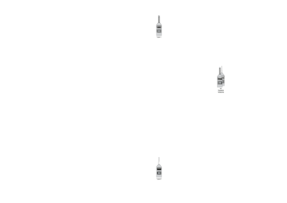
The CEL-225/3 Preamplifier can be identi-
fied by the black key line that should align
with a similar line on the sound level me-
ter. The CEL-225/3 Preamplifier is a devel-
opment of the CEL-225 used with earlier
sound level meters such as the CEL-275
and CEL-275/2 (which have no key line).
The preamplifiers have a similar appear-
ance, but function in a different way, so
that although no damage would occur,
they should not be substituted for each
other when measuring sound levels.
When an earlier preamplifier is used with
a later sound level meter, the noise floor
for linear noise measurement will be
raised to about 70 dB. If an older series
of Type 1 sound level meter is used with
a CEL-225/3 Preamplifier for sound level
measurement, the instrument stabilisa-
tion time will be increased to at least
three minutes. Therefore, it is not recom-
mended to mix old and new versions.
When vibration measurement and analy-
sis is to be undertaken by a Type 1 instru-
ment, both types of preamplifier may be
used to accommodate a CEL-3025 Vibra-
tion Attachment. This is screwed on in
place of the microphone to accept input
signals from an accelerometer.
Type 2 Microphone
The standard Type 2
1
⁄
4
diameter prepo-
larised electret microphone capsule is
permanently attached to a low noise am-
plifier to form a CEL-230 Microphone/Pre-
amplifier Unit that plugs into the tapered
end of the sound level meter. The charac-
teristics of the microphone satisfy the
measurement requirements for both ran-
dom incidence (ANSI standards) and free
field (IEC standards).
For vibration measurement and analysis
with a Type 2 instrument, the CEL-230
Microphone/Preamplifier Unit must be re-
placed by a CEL-225/3 (or CEL-225) Pre-
amplifier which accommodates a
CEL-3025 Vibration Attachment screwed
on in place of a microphone to accept in-
put signals from an accelerometer.
Both types of microphone can be used re-
mote from the instrument when the pre-
amplifier is connected to the Sound Level
Meter via an extension cable. C4493/5
(5 m), C4493/10 (10 m), and C4493/20
(20 m) are standard cables, and a maxi-
mum length of 100 m can be delivered.
The C6602/0.3 (3 m) Flat Ribbon Cable
can be used to carry microphone signals
through door or window closures.
Input signals can be accepted from other
sources. For example when a CEL-216
Line Adaptor is used with a Type 1 instru-
ment or a CEL-316 Line Adaptor with a
Type 2 instrument, AC input signals with
a maximum level of 22.5V
pk-pk
can be fed
in from a tape recorder, (and 21V
pk-pk
AC
signals can be applied via the auxiliary
socket).
As can be seen from the block diagram in
Figure 1, the input from the preamplifier
can be switched to pass to the wide
range RMS detector through a variable
gain amplification stage with linear re-
sponse on A & B versions and the CEL-
493/3, and C-weighted on C, D & E
versions), or it may be passed through an
A-weighted filter that meets the require-
ments of IEC 651 Type 1. Linear, A- or C-
weighted signals are passed via a CAL
control, and may also be passed either to
the internal filter sets of a CEL-266/3 or a
General CEL Sound Level Meters Handbook - Page 5