4 input connections, Sensus data logger, 1 wire preparation and insertion – Casella CEL Nomad portable weather station User Manual
Page 52: 2 standard sensus settings for nomad systems
7.4
Input Connections
Nomad Weather Stations are normally delivered with all required channels
connected to the Sensus unit. However, in the event of cables becoming
disconnected, the following sections give guidance for re-connection.
Remove the connector cover plate to gain access to the input
connector array. It consists of 3, 4 and 5-way detachable connector blocks to
which sensor outputs are wired. The combination of spring-clamp technology
and plug-in modules allow for rapid and secure attachment of a variety of
sensors.
Channel numbering starts from the left-side, bottom-row and
alternates between the bottom and top row, from left to right. In addition the
pins of each connector are numbered from left to right. A copy of this
connector/pin assignment diagram is located on the reverse of the connector
cover plate for reference in the field. (Also see Figure 28: Chapter 9.)
7.4.1
Wire Preparation and Insertion
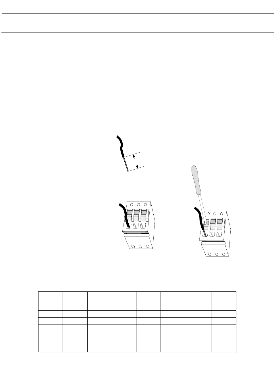
To insert a wire into a
spring terminal, first strip
back the insulation
leaving 10 mm of bare
wire exposed as shown in
Figure 21.
Using a small
flat headed screw- driver
(or similar) fully depress
the orange plunger
located above the hole
into which the wire is to
be inserted and insert the
wire into the hole as far
as it will go, as shown in
Figure 22.
Release the
orange plunger and the
wire is held captive by
the connector (Figure 23).
A gentle tug on
the wire will confirm that
it is held firmly.
7.4.2
Standard Sensus Settings for Nomad Systems
Table 3: Standard configuration and channel limits used for Nomad Systems.
Channel
1
2
3
4
5
6
7
Descrip-
tion
Rainfall
Wind speed Pressure
Direction
Air
temperature
Humidity
Solarimeter
Units
mm
m/s
mbar
degrees
o
C
%RH
W/m
2
Type
Counter
Analog
Analog
Analog
Analog
Analog
Analog
Informa-
tion
Pulse count
Reset at
midnight
Frequency
Reset on
scan
Single
ended
Gain x 1
No current
source
Single
ended
Gain x 1
No current
source
Single ended
Gain x 1
No current
source
Single
ended
Gain x 1
No current
source
Single
ended
Gain x 10
No current
source
Sensus Data Logger
Stripped
Conductor
i
01083
10 mm
Figure 21: Stripped
conductor
Use a small
screwdriver to
depress the
orange clamp
while inserting
the stripped
end of the
conductor
i
ii
iii
iiii
iiiii
iiiiii
iiiiiii
01084
Figure 22 :
Depressing clamp
while inserting
Remove the
screwdriver to
release the
clamp and
grip the
conductor
i
ii
iii
iiii
iiiii
01085
Figure 23: Conductor firmly
held
Page 52 of 68
NOMAD Portable Weather Station
Users Handbook