Casella CEL Sensus data logger unit User Manual
Page 23
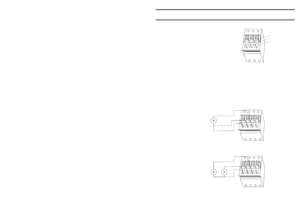
5.5
Counter 3-way Connectors
Input Connections
01075
0V
Cx
+V
Figure 11: 3-way connector
Figure 13: 2-single-ended signals
connected to 4-way analog
Figure 12: Differential connection to
4-way analog
01076
?
?
?
?
01088
?
?
?
?
The next 2 connectors of each row of
the connector array are dedicated to
counter channels. They have the
following pin assignments.
3-way connectors - CNT1 to CNT4
0 V
Analog signal ground reference,
Cx
Counter input,
+V
Permanent 13.8 V supply for sensor
excitation This excitation voltage is
common to all counter sensor connectors.
5.6
Connection Examples
The following set of figures show wiring schemes for some of the more
common input configurations:
5.6.1 Differential Input
5.6.2 Single-ended Inputs
SENSUS Digital Data Logger -
Users Handbook
Page 23 of 44