Casella CEL Sensus data logger unit User Manual
Page 34
9.
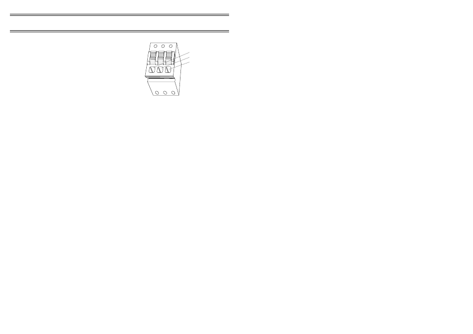
ANALOG OUTPUT
The Sensus Logger provides two analog
signals derived from internal PWM (pulse
width modulation) circuitry. These signals
can be accessed from the connector array as
shown in Figure 22.
These PWM outputs directly mimic
the value contained in a specified data
channel. As the data value changes, the
PWM output also changes to match it.
The following points should be
noted about these PWM outputs.
¤
The data value is interpreted as meaning volts, that is a data value of
0.5 will generate a voltage of 0.5 V.
¤
Only a positive signal can be generated by the PWM circuitry and
this is limited to between 0 and 5 V.
Data values below zero will be limited to zero and those above 5 will
be limited to 5 V.
¤
The resolution of the PWM output is fixed at 10-bits (0 to 1023)
giving a voltage resolution of 4.88 mV.
¤
While the PWM outputs are updated every 50 ms, the data channel
it mimics is updated at most only once a second.
¤
Excessive loading of the PWM output may result in reduced
amplitude and possibly oscillation.
Depending on the length of cable, an external buffer may be required.
Analog Output
01092
0V
A1
A2
Figure 23: The PWM
connector
Page 34 of 44
SENSUS Digital Data Logger -
Users Handbook