Casella CEL Sensus data logger unit User Manual
Page 25
6.
COMMUNICATIONS
The Sensus Logger is fitted with several communications interfaces, two RS
232 and one RS 485. These interfaces allow both control of the logger via
different media and data to be logged from other instruments with similar
interfaces.
6.1
RS 232 Command
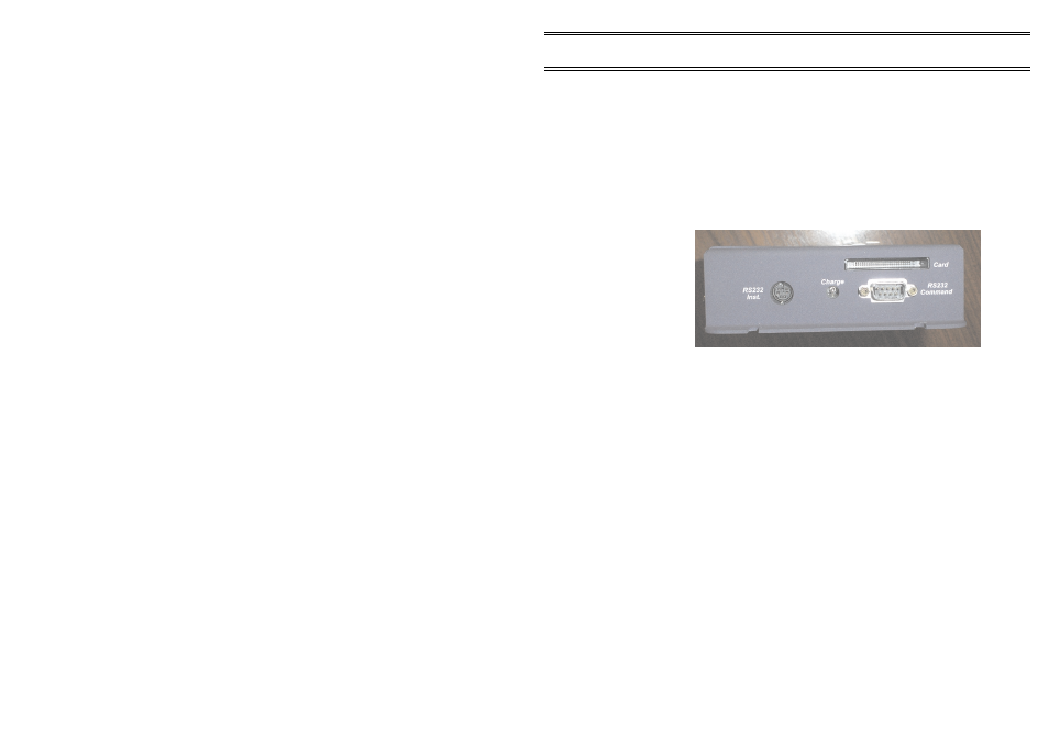
The primary command interface to the Sensus Logger is located on the right
hand end of the logger case, marked RS 232 Command". This 9-way D-type
connector has the same pin-out as a similar 9-way connector found on most
modern PCs.
The pin connections for the RS 232 Command - 9-way D-type
connector are as follows.
Pin
Assignment
2
Receive data (out)
3
Transmit data (out)
4
DTR (out) (linked internally to 7)
5
Ground
7
RTS (out) (linked internally to 4)
8
CTS (in)
It is to this port that a PC is usually connected in order to program/interrogate
the logger. The Sensus Logger is shipped from Casella CEL with this primary
command interface set to the following parameters:
Default parameters - Primary command interface
Baud rate
9600
Data bits
8
Parity
None
Stop bits
1
Handshake
None
All of these parameters may be changed using commands built into the
logger software interface.
The same command channel is also accessible from the connector
array. This time the interface signals appear on a 5-way spring terminal block.
This is of use where power and communication are supplied via a
fixed cable. The communications signals can be connected to a 9-way D-type
connector without the need to prepare the ends of the cable.
Communications
Figure 17: RS 232
Command and RS
232 Instrument
interfaces
SENSUS Digital Data Logger -
Users Handbook
Page 25 of 44