Connecting devices, Input devices / sources, Connecting display devices – Presentation Switchers PS550 User Manual
Page 9
Page 9
Series 500 Installation Guide
Connecting Devices
Input Devices / Sources
Input Devices / Sources
Connect input devices or audio-visual sources as you would most AV Receivers. In most cases,
one source is connected per input board assembly and includes both the video and audio com-
ponents.
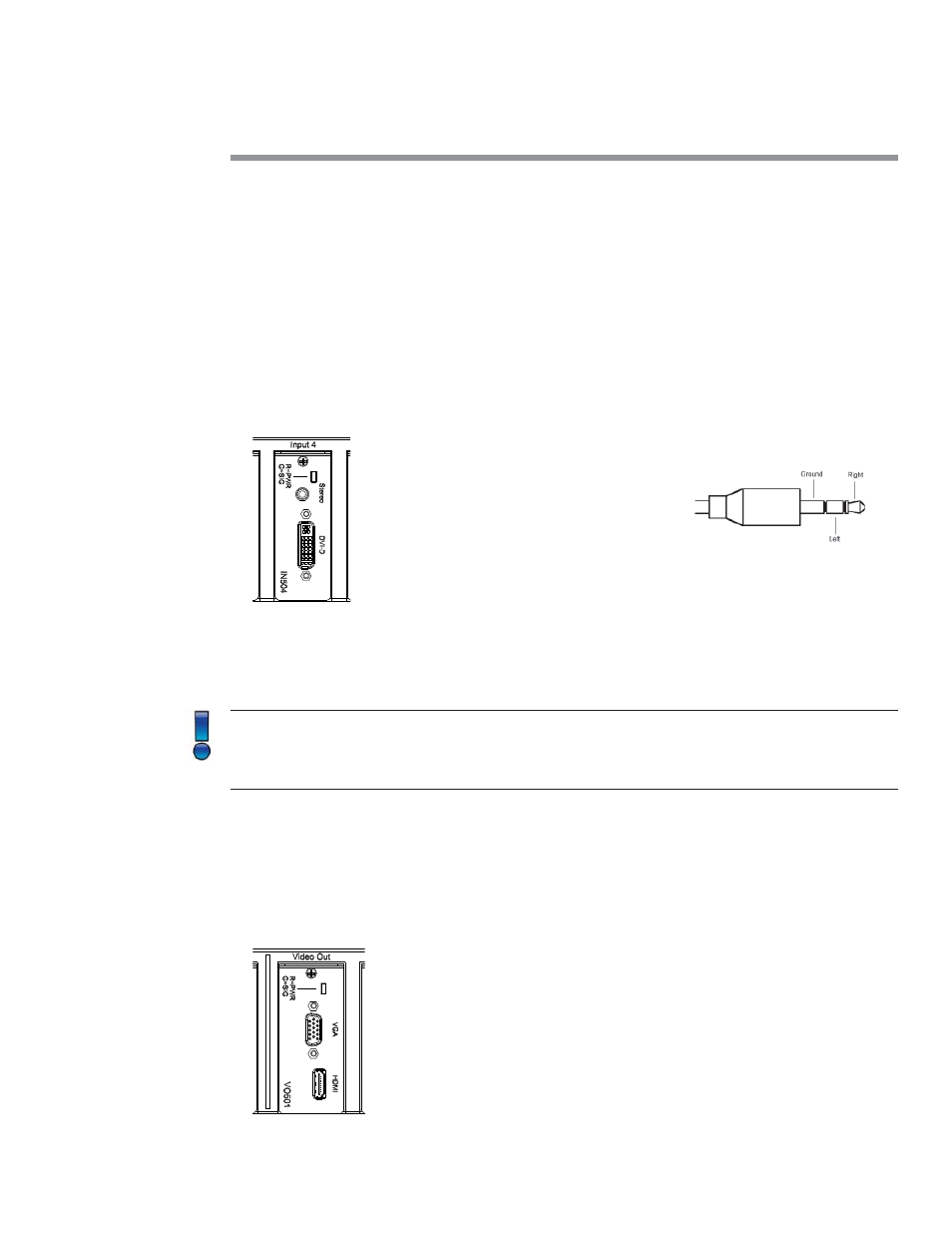
In the example above, a DVI-D board, part number IN504 in this case, is located in input slot
number 4. Connect the video por on to the DVI connector and the audio component to the
3.5mm connector located just above the video connector. This device is now considered “Input
#4”.
Note: The LED located just above the stereo connector will illuminate red when power is
present on the card. The LED will illuminate green when an ac ve video signal is recognized
on the DVI video connector. This LED is present on most input board assemblies.
Con nue the process of connec ng input devices un l all sources are a ached.
Connecting Display Devices
Connecting Display Devices
By default, the Series 500 presenta on switchers are equipped with dual HDMI and VGA con-
nectors as shown in the image below.
3.5mm Connector