Devices – TEKVOX TekManager Comprehensive User Manual
Page 30
30
DEVICES
Initially, a selection for the model TekMonitor to
program, TEK1 or TEK2 must be made. The
default is TEK1, but ensure the appropriate
model is selected before storing the final data
into a TekMonitor or as a Template file.
For a TekMonitor to communicate with a device it
must first be told what device it is to
communicate with. This is made possible by the
selection of a device driver. To select a driver,
make certain that the Serial RS-232 is checked,
and then click-on the
“Select Driver” button. The
Select Driver dialog appears which allows for the
selection of projectors, plasmas/LCD monitors,
and control systems. First select a Manufacturer,
and then a Model. To view information about this
device, click-on
“notes”.
Hovering over the Inputs and Outputs of the TEK 1 image with the mouse, displays information about the
connection. The TEK 2 contains an additional Serial Port which may be enabled.
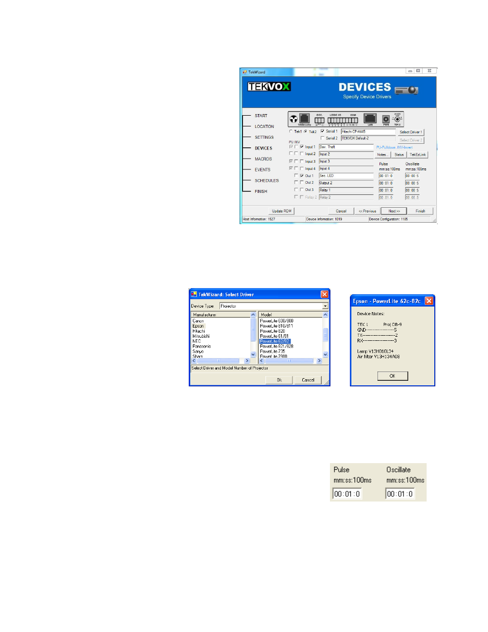
TekWizard - DEVICES
Select Driver and Notes Dialog
There are four Logic Inputs, two
Digital Outputs, and two isolated
Relays on a TEK 1, or for Logic
Inputs and three Digital Outputs on
the TEK 2. From the Device
Settings, you are able to assign
names, and enable or disable them
by the checkmark. Logic Inputs are
used to get status from a device
like a switch, occupancy sensor, or a connection to ground. Additionally, these input types have only two
states; Open/High/Disconnected (Off), or Closed/Low/Connected (On). Any change in a state on these
inputs causes an event to occur which may then be assigned to a Macro for subsequent processing.
Digital Outputs, however, are used to control devices that do not require an isolated ground like an LED.
Finally, Relays are utilized (TEK 1) to control devices that require an isolated ground such as screens and
controllers. Options are provided on the TEK 2 for inverting the input or output signals, and defining pull-
up or pull-down termination of the logic inputs. These are disabled on the TEK 1.
The Digital Outputs and Relays can be; Turned On, Off, Toggled, Pulsed,
Oscillate, or Stopped. To control the Pulse and Oscillation times, an
interval time value entry is used. This time entry allows for the setting of the
time in minutes, seconds, and/or 100 millisecond increments. The
maximum allowable setting is 60:59:9.