Encoder power grounding, Encoder cable length (user supplied) – Adept SmartMotion User Manual
Page 39
MP6 Encoder (MP6-E) Panel Wiring
Adept SmartMotion Installation Guide, Rev. C
39
Adept recommends using a linear power supply instead of a switching power supply. If a
switching power supply is used, make sure to meet the minimum current requirements.
Encoder Power Grounding
Because the 75175 input circuits on the sMI6 have a common-mode input range of +/-12V,
the nominal differential signal swing of 0 to 5V must remain within common-mode input
range. Since a separate power supply is used to power the encoder RS-422 (or
single-ended) drivers, the common of the separate supplies must share a common ground
reference with the voltage supply into the sMI6. Thus, it is very important that the
common signals for these separate supplies be connected to the common of the 24V
plug-in terminal on the front of the sMI6.
If an older MI6-based system is being retrofitted with the sMI6, a modification to the
encoder power supply circuit may need to be made to provide this common power
supply connection. In some cases, new wiring must be provided. For example, the
Yaskawa Sigma amplifiers provide an “SG” or signal ground wire in the “CN” connector
that may not have been needed on the MI6. Since this SG ground must now be connected
to the sMI6 common for differential-signal common-mode reference, a new connection
might have to be made.
The DC power supply common for the internal voltages, including the 5V for the
differential receivers, is connected to the frame ground of the sMI6 internally. The shield
for the sMI6/MP6E cable is also connected to frame ground at the sMI6 XENCODER
connector. Thus, one can sometimes provide the common ground reference at the MP6E
Encoder Power terminal block by connecting pin 2, User's Encoder Power Supply Return
“RTN”, to pin 3 Cable Shield “SHD”. See
Terminal can thus serve as the common ground wiring point on an encoder power system
of separate encoder voltage sources.
Encoder Cable Length (User Supplied)
Because encoders are not supplied with the system and output circuitry varies between
different encoders, it is not possible for Adept to specify a maximum cable length.
However, it is good practice to keep the encoder cable length to a minimum. This practice
helps to improve noise immunity and reduces the risk of encoder signal problems.
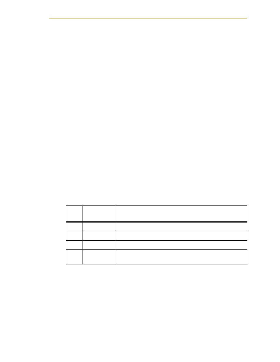
Table 2-8. MP6-E Power Connectors (one per MP6-E)
Pin
Signal
Abbrev.
Description
1
PWR
Encoder voltage supply
2
RTN
Common (return) for the above voltage
3
SHD
Shield for power cable
4
GND
Ground for all MP6-E shield connections. Connect this to your
ground point.