Figure 4-8. category 1 e-stop circuit – Adept SmartMotion User Manual
Page 55
Emergency Stop Circuits
Adept SmartMotion Installation Guide, Rev. C
55
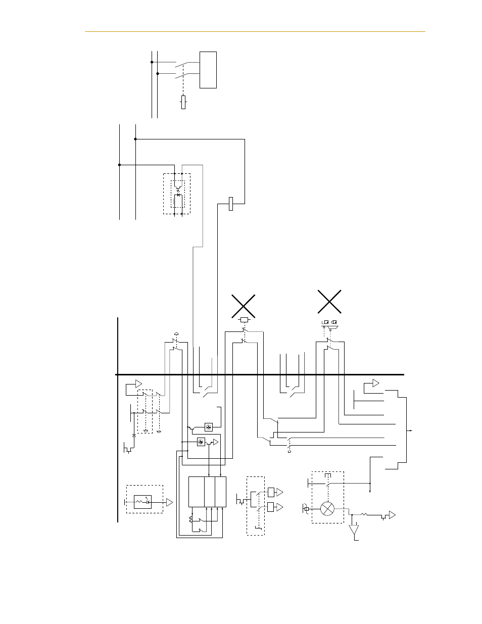
Figure 4-8. Category 1 E-Stop Circuit
Logic cyclic
chec
k state
machines
Channel 1
Channel 2
ES1
ES2
Inter
nal Connections
User S
u
pplied Connections
E-Stop
, High P
o
w
er On/Off
, and MA
N
U
AL/A
UT
O Controls f
or
CIM-2
V
ersion of Smar
tController
FM
F
ront P
anel
E-Stop
Enab
le
MCP
Channel 1
EST
OPSRC
Channel 2
User E-Stop Indication
User E-Stop and
Gate Inter
loc
k
(J
u
mper closed when
not
u
sed, MUST open
both channels
independently if
u
sed.)
EST
OPSRC
ES1
ES2
ES2
ES1
User Man
u
al / A
u
to Indication
(Man
u
al = Open)
MCP4
Enab
le
Switch
Man
u
al/A
u
to
Enab
le
MM1
MM1
MM2
MM2
XUSER-22
XUSER-23
XUSER-10
XUSER-9
XUSER-17
XUSER-16
XUSER-3
XUSER-4
XUSER-20
XUSER-21
XUSER-
8
XUSER-7
XUSER-15
XUSER-14
XUSER-1
XUSER-2
XFP-1
XFP-9
XFP-2
XFP-10
XUSER-6
XUSER-5
XUSER-1
8
XUSER-19
XSYS-9
XSYS-1
XSYS-7
XSYS-6
XSYS-3
XSYS-2
XSYS-5
M
u
ted Saf
ety Gate
- Acti
v
e in a
u
to mode
only
(J
u
mper closed when
not
u
sed)
EST
OPSRC
E-Stop
A
u
to 2
E-Stop
Man
u
al 1
XSYS signals go to PDU or MAI-2 when req
u
ired (
N
o User Connection)
E-Stop
Reset
E-Stop
A
u
to 1
E-Stop
Man
u
al 2
24
V
5
V
V
+
High
P
o
w
er req
u
est
High
Po
w
e
r
On / Off
4.7
0.24
V
XFP-6
XFP-5
XFP-14
XFP-13
- +
V
+
b
u
rned o
u
t
b
u
lb notify
(pre
v
ents High
P
o
w
er enab
le)
HP Light
Enab
le)
6
V
, 1.2
W
b
u
lb
F
ront P
anel
24
V
F
ront P
anel
MM1
XFP-3
XFP-4
XFP-11
XFP-12
MM2
Man
u
al/A
u
to K
e
ys
witch
- Man
u
al = Open (|)
- Man
u
al => (<250 mm/s)
- A
u
to => 100%
24
V
5
V
F
ront
P
anel
System
Po
w
e
r
LED
XFP-7
XFP-15
Gr
n
J
u
mper
See
N
ote
J
u
mper
See
N
ote
See
N
ote
N
ote: These three f
u
nctions:
Line E-Stop, M
u
ted Safety Gate,
and MCP Enable, will only be
sensed by software. They will not
tu
rn off High Power directly.
24
V
DC
0
V
DC
KA
+
HPE
MP6-M
–
Example CE E
N
495-1 Categor
y B or 1
Emergency Stop circ
u
it f
or A
u
to Mode
,
sho
wing simple po
w
er c
u
toff to
User Amplifier's High P
o
w
er section.
This will enab
le High P
o
w
er when
V
+ calls f
or it.
L2
L2
L1
L1
User Amplifier
KA
Line E-Stop
(Exter
nal User
E-Stop system)