Vent configuration – Avalon Firestyles 900 PI-1992 User Manual
Page 19
PAGE 19
PREPARATION FOR INSTALLATION —
PELLET INSERT (cont.)
NOTE: The fireplace cavity must be thoroughly cleaned prior to installation. It should be cleaned with a wire brush or
scraper and then painted with a latex paint to eliminate the possibility of odors from the fireplace being circulated into
the house by the room air fan of the pellet insert.
For your safety, examine the fireplace and chimney prior to installation of the pellet insert to determine that they are
free from cracks, loose mortar, creosote deposits, blockages, or other signs of deterioration. If evidence of
deterioration is noted, the pellet insert should not be installed until after repairs have been made. Any opening
between the masonry of the fireplace and the facing masonry must be permanently sealed.
Your pellet insert is listed for installation into masonry fireplaces, and is approved to be installed with or without
positive or direct chimney connection.
Your pellet insert is also approved for installation into metal or zero-clearance (Z.C.) fireplaces. Metal or Z.C.
installation requires a full reline with a 3" stainless steel single-wall pipe or a flexible liner.
Your Avalon 900 Pellet Insert appliance comes completely assembled, with the exception of the switch box, panels
and panel trim. Options available for the different types of installations are:
1.
Adjustable Front Insert Support.
2.
Panels - 8", 10", or 12"
3.
Ceramic Log
The above items come boxed separately and require assembly.
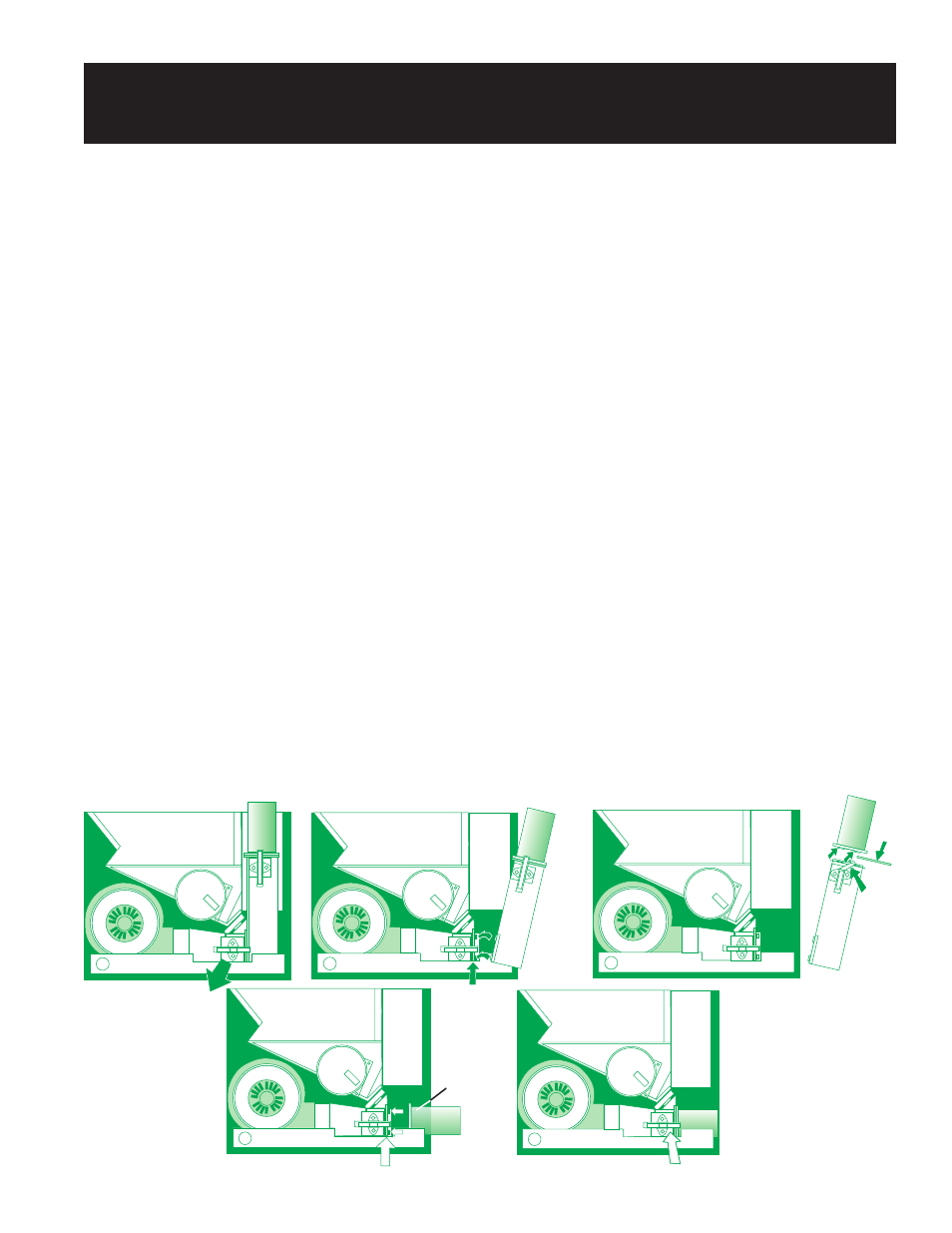
VENT CONFIGURATION:
The 900 Pellet Insert is equipped with a dual vent configuration. It can be vented vertically or horizontally. Before
installing, you must determine which configuration will best suit your installation.
The unit comes set up for a vertical installation (Fig. 12-A). To change it to a horizontal venting configuration,
remove the 1/4" hex head bolt and clamp holding the vertical vent to the base of the unit, next release the spring clip
on the side of the lower vent duct , (Fig. 12-B) and remove the vent assembly then release the spring clip holding the
round portion of the vent to the rectangular portion (Fig. 12-C). To complete the change over, clip the round portion
into the lower vent duct bracket (Figs. 12 D & E).
NOTE: Make sure that the gaskets are not damaged and are in the proper position before latching the spring clip.
UNLATCH FIRST
NOTE
TABS
UNLATCH
SECOND
REMOVE
GASKET
TAKE OFF
VERTICAL FLUE
ATTACHMENT
NOTE
TABS
LEAVE GASKETING
IN PLACE
NOTE
TABS
MAKE SURE
GASKETING
IS IN PLACE
RELATCH
FIG. 12-B
FIG. 12-C
FIG. 12-D
FIG. 12-A
FIG. 12-E
NOTE
TABS