Insert installation specifications - (cont.) – Avalon Firestyles 900 PI-1992 User Manual
Page 22
PAGE 22
INSERT INSTALLATION SPECIFICATIONS - (cont.)
DIRECT CONNECTION: (Continued)
4.
A hole must be cut in the plate to allow the chimney connector to pass through from the appliance into the
chimney. Mark the hole position on the plate so that the center of the hole is in line with the center line of the
appliance flue. A flexible stainless steel connector works best if an offset is required.
5.
Position the plate in the firebox where the measurements were taken. Secure the plate with screws through
the holes in the lip, and seal around the outside edges of the plate with fiberglass insulation, furnace cement,
or both.
6.
Insert the chimney connector (flexible or rigid single-wall stainless steel, 3" diameter and at least 24" long) up
through the hole in the plate and damper opening into the chimney. Seal where vent passes through block-
off plate. This should be done on completion of connection.
NOTE: Masonry fireplace installations require a direct connection or positive (complete reline) connection to
the chimney flue. With a direct connection a block-off plate made of metal or other non-combustible material
(i.e. Kaowool or high temperature fiberglass insulation) must be used at the damper location and sealed
airtight. The singlewall pipe or flexible liner must extend past the block-off plate or insulation by one (1) foot
(305 mm) or to the first flue tile if the chimney has a tile lining.
With a positive connection, the block-off plate at the damper location is optional, but a sealed cover plate is
required at the top of the chimney. A positive connection (complete reline) is recommended for ease of
cleaning.
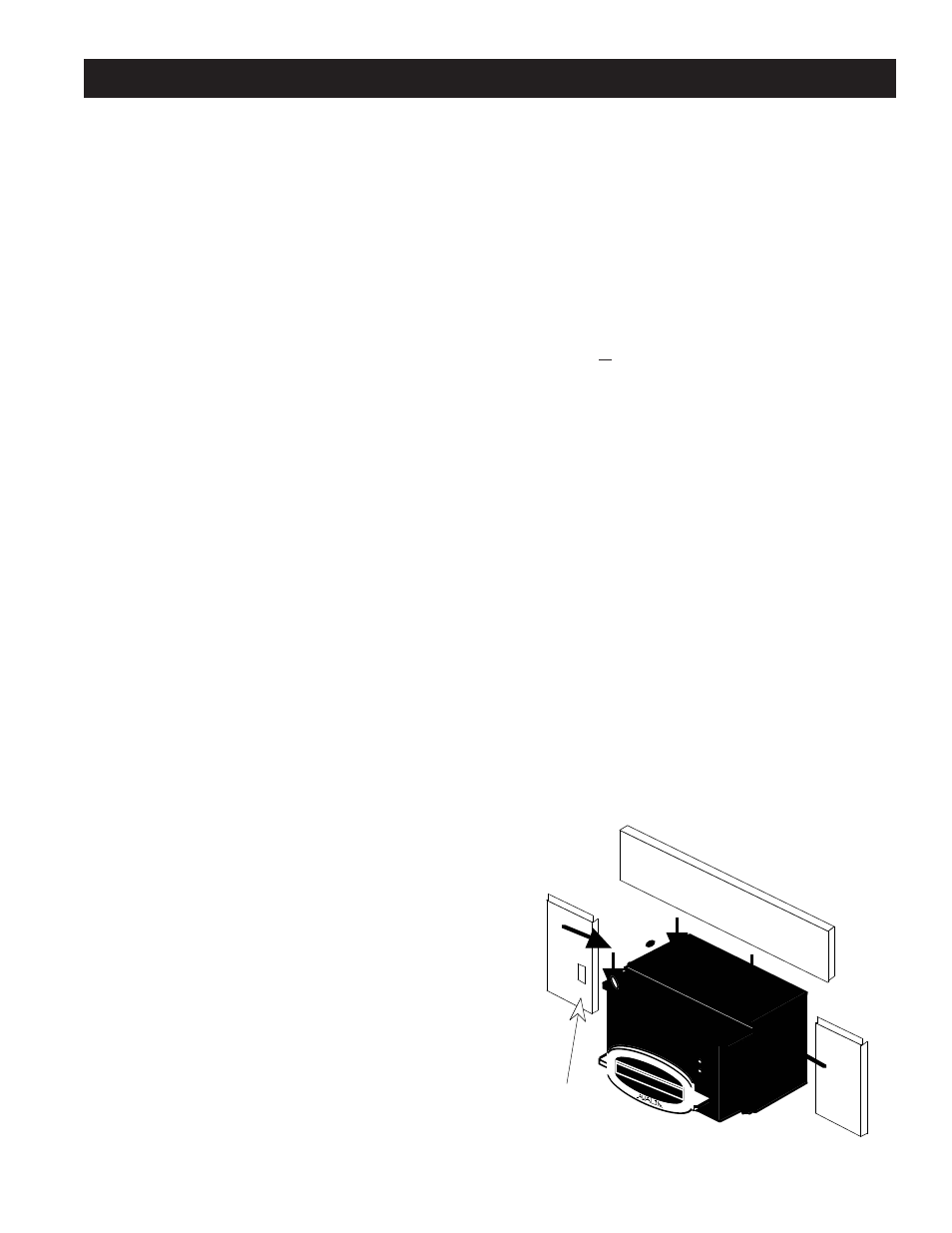
PANEL INSTALLATION:
7.
Lay a protective covering such as a towel or blanket on the floor to protect the floor and the panel finish. Remove,
from the box marked Panels, one top panel and two side panels. Make sure that the panels are large enough to
cover the fireplace opening. NOTE: Route the power cord out of the fireplace so it exits through the lower outside
front corner of the fireplace opening. DO NOT ROUTE THE POWER CORD UNDER THE UNIT.
8.
Align the side panels with the sides of the unit. The panels are notched and simply clip onto the sides of the unit.
9.
Unwrap the Switch Box (shipped inside the firebox of the appliance) and clip it into the panel. The Power Switch
should be at the top and the Blower Control at the bottom. This must be done prior to the installation of the top
panel.
10.
Position the top panel over the unit. Align the clips and slide the top panel over the side panel flanges and the top
of the unit. Press down firmly to make a secure fit.
11.
Place the trim face down on the floor, as it would appear on the unit. Place the corner brackets in the appropriate
slots, insert the set screws and tighten firmly.
12.
Slide the completed trim assembly over the panels.
You may wish to use two-sided tape at the ends of the
trim to hold it firmly against the bottom of the side
panels.
13.
Push the assembled insert, panels and trim into the
fireplace until the spacers make contact with the face of
the fireplace. Be careful not to scratch the hearth.
NOTE: Maintain at least a 3/8" air gap around the
outside edge of the panels. This allows air to flow
around the unit. If this gap is not maintained, the unit
could overheat.
14.
Make sure that the insert is square in the fireplace
opening.
Switch Box
Attaches to
Side Panel Here