Insert installation specifications (cont.), Gh j – Avalon Firestyles 900 PI-1992 User Manual
Page 21
PAGE 21
INSERT INSTALLATION SPECIFICATIONS (Cont.)
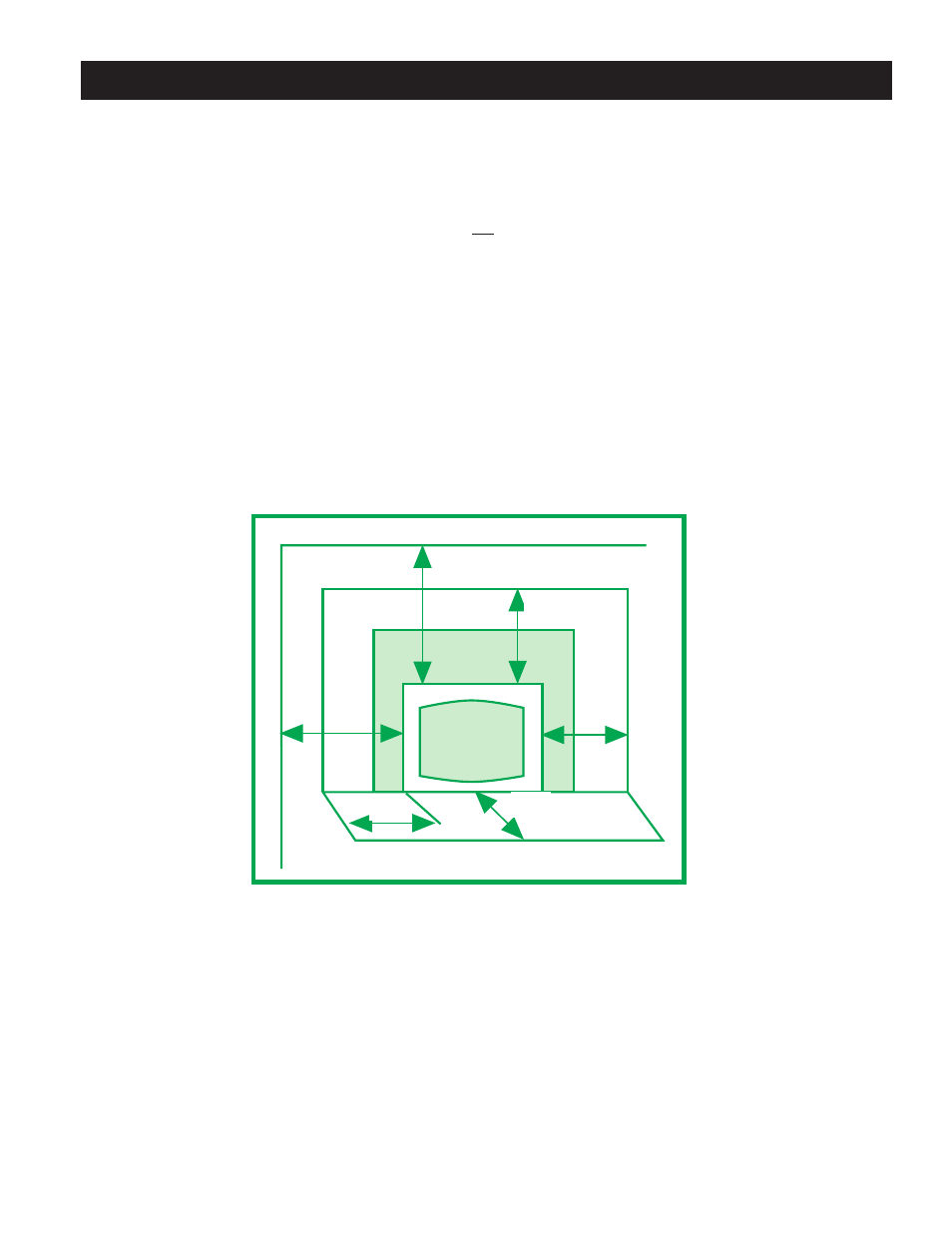
FLOOR PROTECTION: (Fig.10 )
E.
Front
0" (0mm)
F.
Sides
0" (0mm)
NOTE: Although a non-combustible hearth extension is not required to extend past the front and sides of
the insert, the insert must be installed on a non-combustible hearth that extends to the front and side
edges of the insert.
CLEARANCE TO COMBUSTIBLES: (Fig. 10)
A.
Adjacent Sidewall
9" (229mm)
B.
Side Facing
8" (203mm)
C.
Top Facing
12" (305mm)
D.
Mantle
13" (330mm)
NOTE: For clearances, use this clearance diagram (fig. 10 ) or the clearance diagram on the
safety label attached to the back of the appliance.
Figure 10
DIRECT CONNECTION:
1.
Make sure the fireplace and chimney are thoroughly cleaned, inspected and repaired where necessary to
make it safe. Paint with a latex paint as explained on Pg. 19.
2.
Wire open or remove the firebox damper.
3.
Measure the area of the firebox below the damper opening and above the lintel. Transfer these
measurements to a piece of galvanized sheet metal (min. 24 gauge) and add 2" to each side. Mark the
position of several holes on each side, to suit your specific installation, and drill 1/4" diameter holes. Next
bend the 2" extended side to a 45
°
angle. The 2" lip with the 1/4" diameter holes will allow you to screw
the plate to the firebox walls.
G
H
J
0"
I
0"
MANTLE
SIDEW
ALL
D
C
B
E
F
A