Ab d h, Gc c h, Freestanding installation specifications (cont.) – Avalon Firestyles 900 PI-1992 User Manual
Page 9: H (0"), Corner wall backwall
PAGE 9
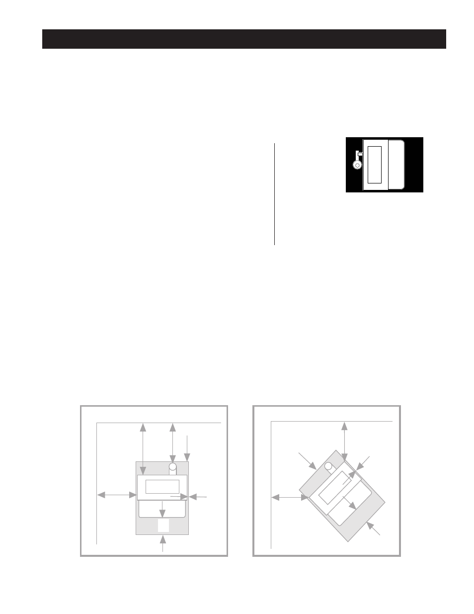
FLOOR PROTECTION: (Fig. 2 & 3)
G.
Front
6" (152 mm) NOTE: Front floor protection is measured from the door opening.
H.
Sides
0" (0mm)
H.
Back
0" (0mm)
NOTE: Floor protector should extend to areas below and 2" (50 mm) to each side of a "tee" when used (See Fig. 6).
CLEARANCE TO COMBUSTIBLES:
INTERIOR VERTICAL FLUE INSTALLATION
Figures 2 & 3
A Sidewall to unit
9" - (229 mm)
B Backwall to unit
11" - (279 mm)
C Corner wall to unit
2" - ( 51 mm)
D Flue vent/chimney
3" - ( 76 mm)
NOTE: Dimension "C" , corner to unit, and "B", backwall to unit, will vary depending on the type and brand of
pellet vent or interior connector used. Always maintain the "D" dimension, pellet vent/interior connector
clearance, when installing this unit. Check your pellet vent/interior connector instructions for information on its
size and clearance required to comustibles. NOTE: Singlewall interior connectors require a minimum 3"
clearance to combustibles.
HORIZONTAL THROUGH THE WALL INSTALLATION OR VERTICAL
EXTERIOR INSTALLATION
Figures 2 & 3
A Sidewall to unit
9" - (229 mm)
B Backwall to unit
3" - ( 76 mm)
C Corner Wall to unit
2" - ( 51 mm)
D Flue vent/chimney
3" - ( 76 mm)
FREESTANDING INSTALLATION SPECIFICATIONS (cont.)
CORNER WALL
BACKWALL
CORNER W
ALL
SIDEW
ALL
A
B
D
H
H (0")
G
C
C
H
H (0")
G
FIGURES 2 & 3
3" Pellet Vent
6" Stovepipe
9" - (229 mm)
9" - (229 mm)
7" - (178 mm)
9" - (229 mm)
2" - ( 51 mm)
2" - ( 51 mm)
3" - ( 76 mm)
3" - ( 76 mm)
VERTICAL
PIPE
ADAPTER