Screen displays - overview – Cadac CDC four User Manual
Page 25
Revision 1 2012-13
CDC FOUR
25
Screen displays - overview
The TFT screen in the Central Control Module displays various information about
the current status of the mixer. The screen may be switched to display any one of
several pages, each of which is concerned with a particular set of mixer functions.
There are six pages available, selected by the page select buttons to the left of
the display:
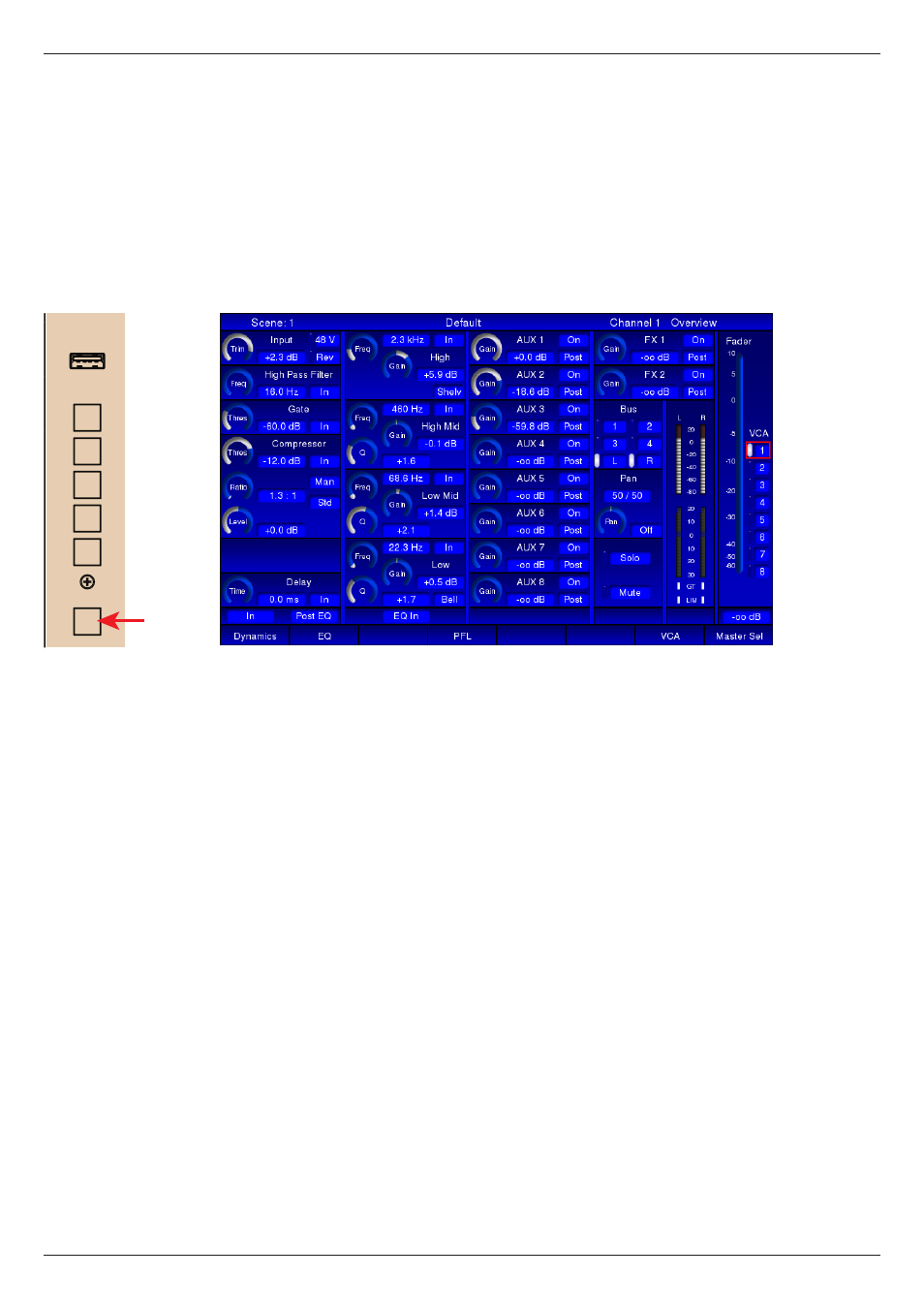
CHN: this is the default view.
The screen shows a representation of a single channel strip. Every control on
the CAM has a “virtual” equivalent on the display, and the page layout follows the
conventional signal flow through a channel. It is divided into five vertical strips, the
first four of which follow the layout of controls on the CAM. The fifth (rightmost)
page strip shows the channel fader and VCA assignment.
The on-screen display always follows the SEL and LAYER selection; thus the
screen provides confirmation of the control settings for the currently selected
channel.
Because the rotary controls in the CAM are 360° encoders, their physical position
is not an indication of the parameter value (as would be the case on an analogue
mixer). However, the Channel page shows all current parameter values. Switch
settings are displayed in textual format and rotary controls are represented as
“analogue” 300° potentiometers, with the actual parameter value alongside in
text.
USB
CENTRAL CONTROL MODULE
METERS
SCENE
FX
ROUTE
SYSTEM
CHN