Cadac CDC four User Manual
Page 56
56
Revision 1 2012-13
CDC FOUR
Release – this works in a similar manner to the Noise Gate’s Release
parameter; after the signal level drops below the compressor threshold,
the gain reduction applied as a result of the compressor action is gradually
reduced. Setting the Release parameter to suit the signal being treated will
generally minimise the effect of “pumping” that compression can produce.
Transfer Characteristic and meters
The Dynamics detail page also provides separate input and output metering for
the gate, compressor and limiter (in the case of the Groups and Aux Sends), which
allows a quick evaluation to be made of the effects of the dynamics processing. A
Gain Reduction meter for the compressor is also implemented on-screen.
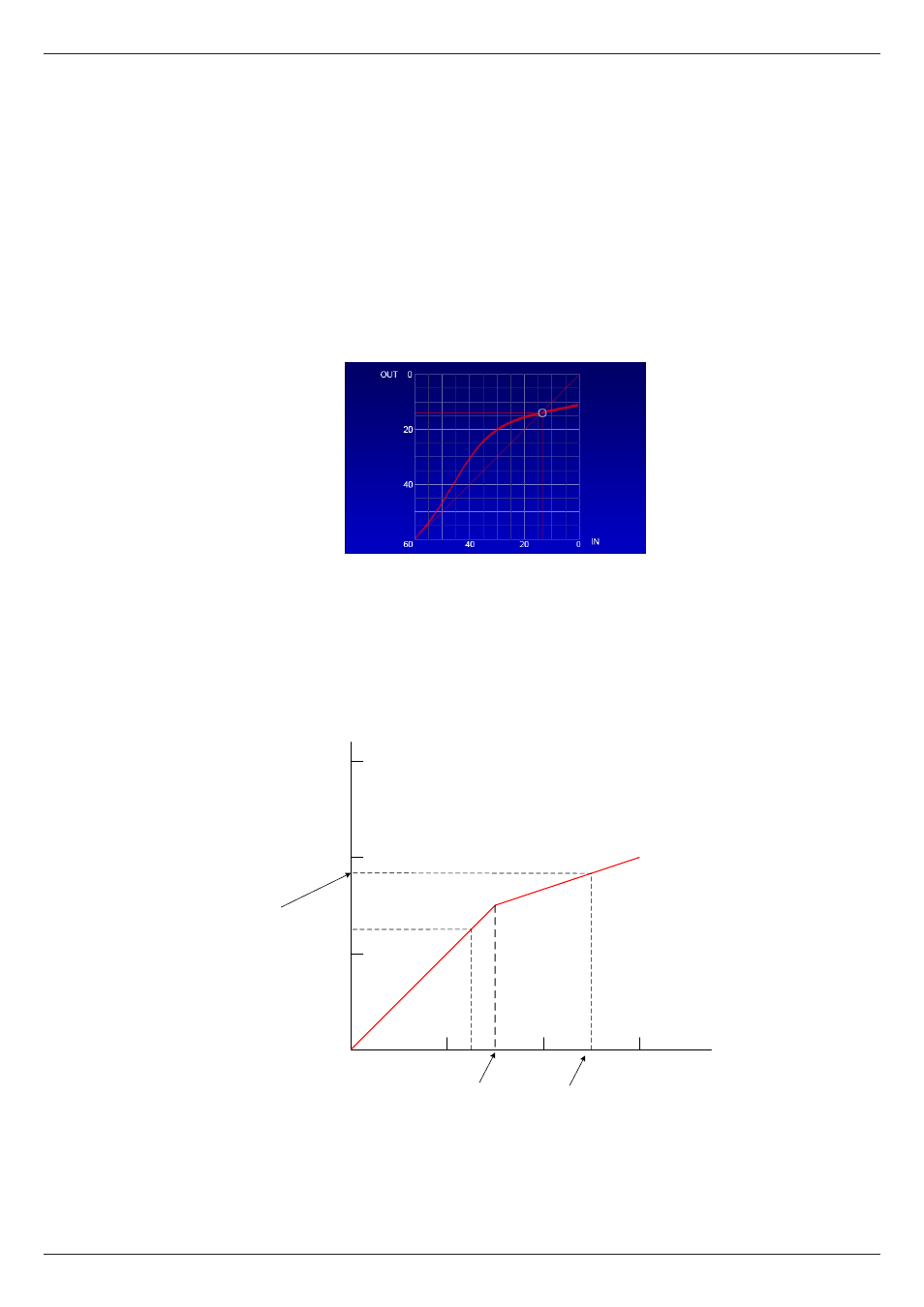
The transfer characteristic displays the relationship between input and output
levels graphically, and shows the effects of the compressor’s Threshold, Ratio
and Level controls. The horizontal (x-) axis represents input signal levels, and the
vertical (y-) axis output levels. The output signal level for any input signal level
can be found by tracing a line vertically from the x-axis at the point representing
the input signal level to the transfer curve, then reading across horizontally to the
y-axis.
-60
0
-20
-40
0
-20
-40
Input level = -10 dB
Output level = -23 dB
THRESHOLD
A
B
With no compressor action (i.e., with the compressor by-passed, or with Ratio set
to 1:1), the transfer characteristic is a straight line at 45° to both axes. The line
becomes “kinked” when compression is applied. In the example above, the input
signal at A is at -35 dB, and hence below the threshold of -30 dB; no compression