Herrmidifier Herrtronic MD User Manual
Page 10
Herrtronic
®
MD Series
I n s t a l l a t i o n , O p e r a t i o n , & M a i n t e n a n c e M a n u a l
10
www.herrmidifier-hvac.com
Controls
The Herrtronic MD Series Humidifier has the capability to utilize
one of three types of control schemes.
1. On/Off
2. Proportional
3. Proportional + Integral
Controls may be supplied by the factory or others. The following
information applies to all controls factory supplied or furnished
by others. All external electrical control circuits are to be con-
nected to the unit using the twelve pole terminal strip located
in the electrical compartment. The terminal strip is accessed
through the side electrical compartment door. Field wiring from
humidistat to humidifier and between safety devices, such as
high limit humidistat and air proving switches, should be 18
AWG stranded or 20 AWG solid wire. If conduit is not used with
the controls wiring, install the black plastic fingered bushing (in
accessory pack) and completely seal with RTV silicone.
Wall devices should be mounted at a height similar to that of a
typical thermostat and should be located in an area that will pro-
vide good representation of the overall space being humidified.
Do not mount wall devices directly in the air stream of a supply
grille or room distribution unit.
Duct control devices should be mounted in a location where the
humidity and temperature are uniform, usually the return duct.
Do not mount in front of the steam distributor or in a mixing,
turbulent, or isolated area.
Duct high limit devices should be mounted downstream of the
steam distributors-far enough that under normal conditions in
the air stream, the steam has been completely absorbed, typi-
cally 10 ft. The device should be located such that it can sense
humidified air as it approaches saturation. Do not mount in dead
air spaces such as inside of corners or erroneous operation may
result.
Air proving devices should be mounted so that they sense air
flow (or the absence of it). Wire the device so that it closes when
air flow is present and will open when there is no air flow. The
purpose of the device is to prove that air flow is present before
steam is distributed into the duct.
The following information and diagrams are shown for each con-
trol scheme. Please refer to the control scheme that your humid-
ifier was set up for and follow the diagram for control circuit con-
nections. The factory-set control type and signal are indicated
on a label adjacent to the controls terminal strip.
Control Circuit Connections
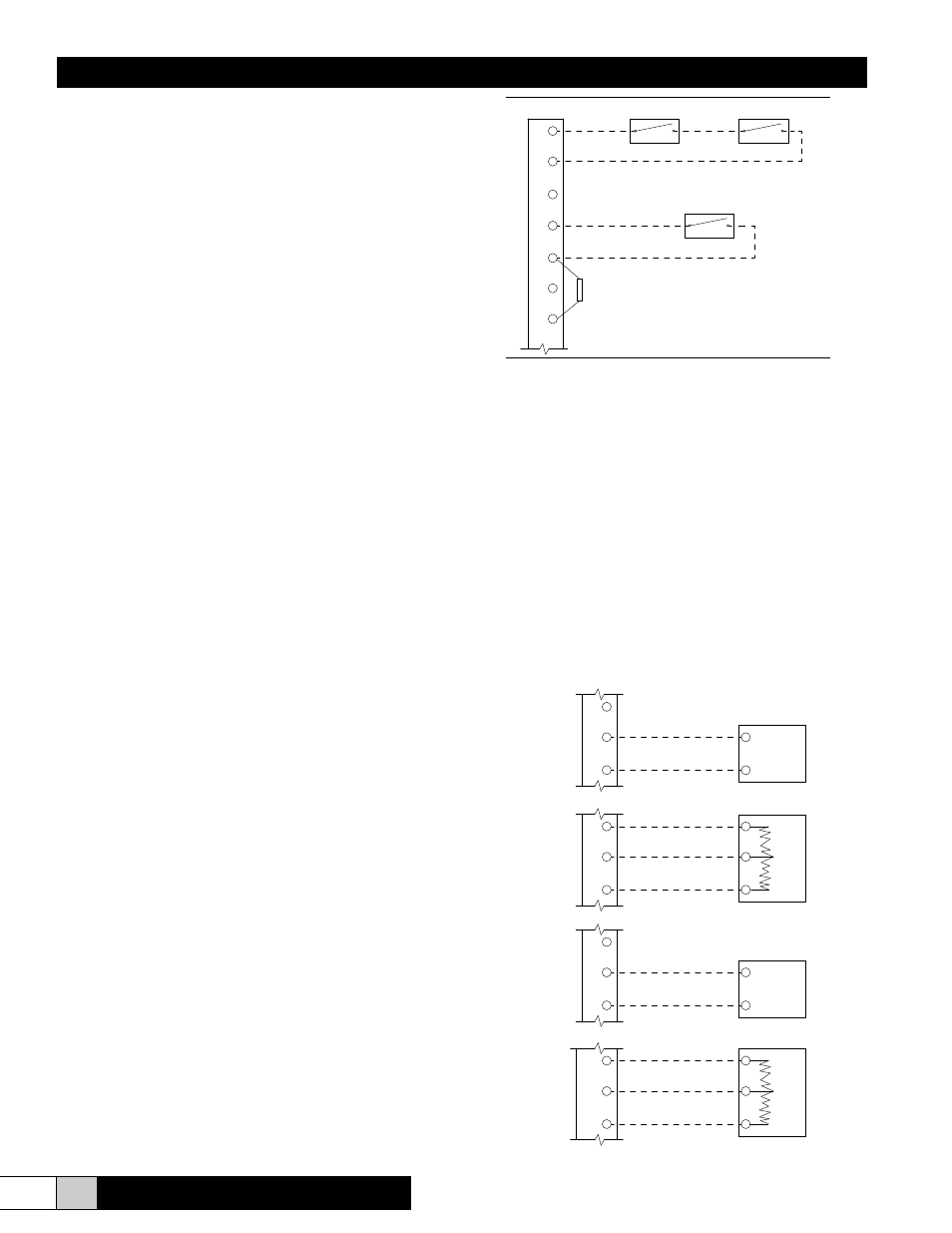
Mode 1 - ON/OFF Operation
1. Control Input - Unit will operate with any two position device
(See Fig. 9). Demand for humidity will close the contact.
2. Limit Input - Unit will operate with any two position device
(See Fig. 9). The humidistat contact will open on humidity
rise.
Mode 2 - Proportional Operation
1. If two position airflow and/or high-limit humidistat is used
wire as shown in Figure 9.
2. Control Input - Interpreted by the humidifier as a demand of
output signal. Input device should be linear. Unit can accept
any VDC or mADC signal within a range of 0-20 VDC or
mADC (See Fig. 10). Unit may also accept a resistive signal
0-135 ohms (See Fig. 11).
3. Limit Input - Unit may accept any modulating input within
the same ranges as the control inputs listed above.
a. Proportional VDC or mADC (See Fig. 12)
b. Resistive (See Fig. 13)
Additionally, a P + I sensor may be used as a limit
input.
c. VDC (See Fig. 16)
d. mADC (See Fig. 17)
1
2
3
4
5
Air Flow Switch
High Limit Stat
Control Humidistat
FIGURE 9
6
7
See Note Pg. 28
68.1 k Resistor
Ω
4
5
_
FIGURE 10
VDC or
mADC
Signal
+
4
5
6
_
FIGURE 11
W
+
R
B
OUT
FIGURE 12
_
8
9
+
VDC or
mADC
Signal
8
9
10
_
FIGURE 13
W
+
R
B
OUT