Herrmidifier Herrtronic MD User Manual
Page 12
Herrtronic
®
MD Series
I n s t a l l a t i o n , O p e r a t i o n , & M a i n t e n a n c e M a n u a l
12
www.herrmidifier-hvac.com
Remote Alarm
The Herrtronic MD Humidifier is equipped with a remote alarm
output. It is a triac output that may be used to energize an exter-
nal relay or buzzer to indicate an alarm condition is present. The
alarm output is activated whenever an indicating fault condition
exists. When units are networked together, the master’s alarm
contacts will close if a fault occurs at either the master or one of
the slave units. The contacts are connected at poles 1 and 2 of
the remote alarm terminal strip 3.
In order to use the remote alarm output with a Building Manage-
ment System, the remote alarm output must be used to energize
a mechanical relay. The contacts of the external relay may then
be wired to an input on the BMS to indicate if an alarm condition
is present. The remote alarm output may not be used like a dry
contact to a BMS.
Do not exceed the contact specifications!
Contact rating:
• 24 VAC - 3.0 A
• 24 VDC - 2.1 A
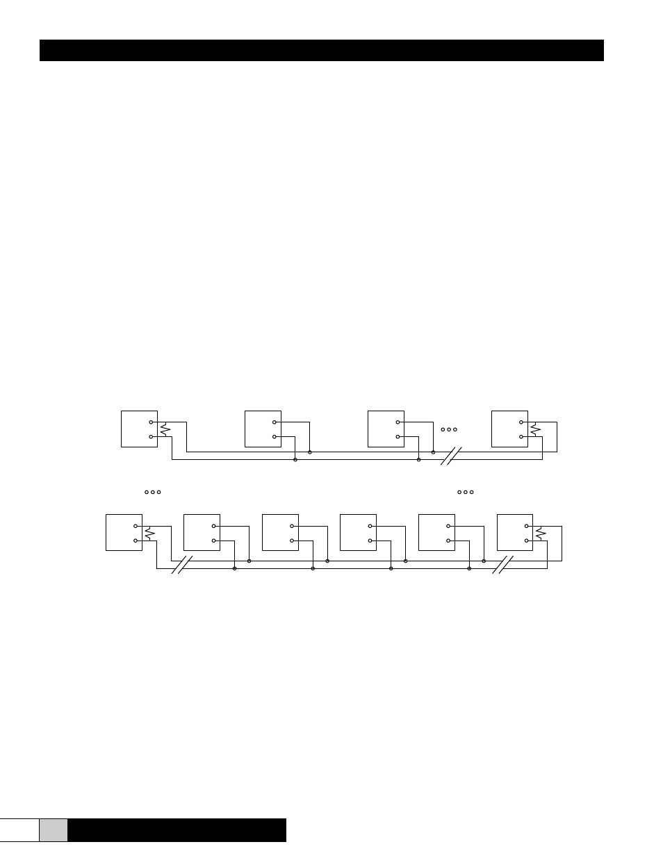
Unit Networking
When networking units together in a master/slave configura-
tion, be sure to maintain polarity between poles 11 and 12 on
all units. Units are to be wired as a parallel circuit. More than
one branch is allowable so that the master unit can be centrally
located (See Fig. 19). A maximum of 29 slave PC boards (29
MDS or MDM units or 14 MDD units) may be configured as a
network. Included in each installation pack is a 120 ohm resistor.
This resistor should be inserted into R28 on the microprocessor
board (see Fig. 32) on the appropriate end units of the chain.
(Refer to Fig. 19)