Hours of operation, Water level output – Herrmidifier Herrtronic MD User Manual
Page 4
Herrtronic
®
MD Series
I n s t a l l a t i o n , O p e r a t i o n , & M a i n t e n a n c e M a n u a l
4
www.herrmidifier-hvac.com
II. UNIT OPERATION
Herrtronic MD: Basic Operation
Controlled humidification requires a very precise control sys-
tem. The Herrtronic MD utilizes a microprocessor to monitor
performance and maintain humidity. Further, the Herrtronic
MD evaluates the operation and alerts the operator to prob-
lem conditions and prevents undesirable operation:
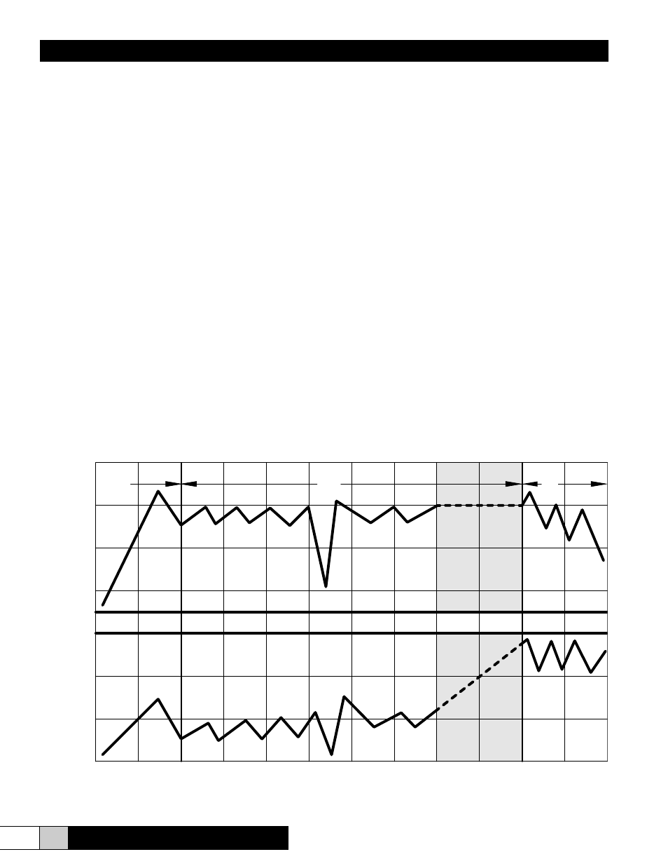
1. Start-up: On initial start-up (prompted by a call-for-hu-
midity), the fill valve opens allowing water to enter the
cylinder. When the water level rises to the electrodes,
current will flow and the water will begin heating. As
the water temperature increases, its conductivity also in-
creases, accelerating the rate of temperature increase.
When the output reaches the “capacity set point,” the fill
valve closes. The output capacity may continue to rise
slightly beyond the “capacity set point.” As the water
boils away, the water level falls. This results in a reduc-
tion in output capacity.
2. Normal Operation: Upon achieving “capacity set point,”
the system begins operation in a steady state mode.
Output capacity slowing decreases until the elapsed “cy-
cle time” opens the fill valve to replenish the water level
until the “capacity set point” output is achieved. As the
mineral concentration in the water increases, the water
conductivity also increases. Accordingly, the rate of boil-
ing increases. Eventually, the rate of boiling reduces the
output capacity below the “low drain threshold” before
the “cycle time” initiates the fill cycle.
At this point, the drain valve opens discarding the min-
eral laden (highly conductive) water, replacing it with
fresh water, that lowers the mineral concentration until
the system is restored to the steady state mode.
The steady state operating mode continues with small
increases in the water level to maintain output capacity
(by exposing new electrode surface).
3. End-of-Cylinder Life: Steady State operation continues
with “fill and boil” and periodic drain cycles with ever in-
creasing water levels. Eventually, the water level reach-
es the cylinder full electrode, representing the maximum
allowable water level inside the cylinder. The system
output begins to decrease since there is no new elec-
trode surface to expose. If the system operates continu-
ously without achieving “capacity set point,” an “end of
cylinder life” fault will be displayed.
Hours of Operation
1.
2.
3.
High Drain
Threshold
Capacity
Set Point
Low Drain
Threshold
Cylinder
Full
Steadily Increase
Water Level
W
ater Level
Output
HERRTRONIC MD: Basic Operation