No faults present in system slave xx has faults, Herrtronic, Md series – Herrmidifier Herrtronic MD User Manual
Page 19
Herrtronic
®
MD Series
I n s t a l l a t i o n , O p e r a t i o n , & M a i n t e n a n c e M a n u a l
19
www.herrmidifier-hvac.com
Diagnostics
The Herrtronic MD humidifier includes built-in diagnostics ca-
pability to identify potential problems, protect the system, and
minimize service/repair time. Should the system detect a critical
condition, a “fault” warning will be displayed on the LCD. Cer-
tain faults prompt immediate system shutdown to protect the
MD unit or ductwork. Other faults allow the unit to continue to
operate but alert the operator to potential problems that require
maintenance. Other faults, which are designed for initial system
tune-up or preventative maintenance, are classified as “non-in-
dicating.” These faults are viewed by pressing the “fault” key on
the control panel. The table reflects all of the faults the system
is capable of detecting. Please note, however, that certain faults
are unique to certain control modes or networked systems and
are only visible where applicable.
During operation, when an “indicating” fault occurs, the word
FAULT will be visible in the lower right hand section of the LCD.
The red fault light will also be illuminated.
If an “indicating” fault has been detected or a preventative check
is being performed, follow this procedure to determine the cause
of the fault:
1. The LCD must be in the MAIN MENU to access diagnos-
tics. Press “FAULT” key to determine the type of fault.
2. Press the up arrow to determine if there is more than one
fault.
3. If possible, correct the condition causing the fault signal or
plan corrective action.
4. Press “ENTER” to clear the fault signal from the display.
When “ENTER” is pressed, all faults registered in the unit
will be cleared. If the condition causing the fault is not cor-
rected, another fault signal will occur.
5. Under normal operating conditions, pressing the “FAULT”
button will prompt the following display:
In a multi-unit network, the master (“00”) unit will indicate a fault
within the entire network. To find the fault(s), follow steps 1 and
2 for the master unit. If the display indicates “No Faults Present
In System,” then neither the Master, nor any Slave unit, has any
faults.
If any slave has a fault, the LCD will read:
Utilize the communications (Menu 4) from the Master to access
the particular slave with fault(s) to determine the fault. (Refer to
communication instructions in the programming section). Press
the “up” arrow button to determine if there is more than one
“slave” that has a “fault.”
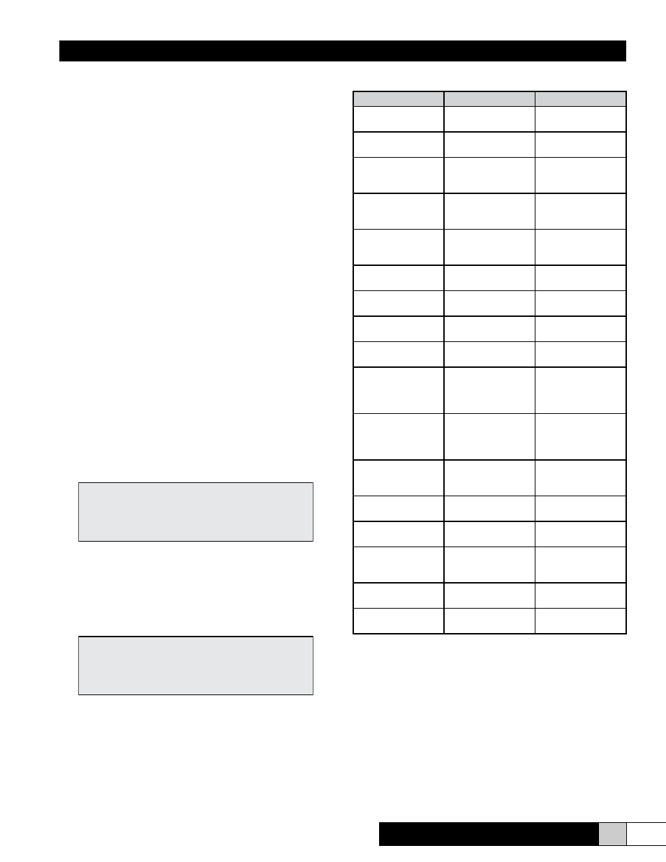
System Fault Conditions
(See Troubleshooting Section for corrective action)
Fault
Operation Status
Comments
Current Overload (4) Shutdown and Drain
Manual Reset(1)
138% of Capacity
Setpoint Exceeded
Contactor Failed (4)
Continued Operation Humidification Re-
quired
Cylinder Full Zero
Current
Continued Operation Humidification
re-
quired; unit not func-
tioning properly
Fill System Fault (4)
Shutdown and Drain
Manual Reset (1)
Fill for 15 min. – can-
not achieve capacity
setpoint or cyl. Full
Zero Electrode Cur-
rent
Continued Operation Humidification
re-
quired, no current
draw
Non-zero Slowly De-
creasing Amps
Continued Operation Defective drain sys-
tem
Non-zero Non-De-
creasing Amps
Continued Operation Defective drain sys-
tem
Non-zero Non- In-
creasing Amps
Continued Operation Defective fill system
Non-zero Slowly In-
creasing Amps
Continued Operation Defective fill system
Cylinder Full
Continued Operation Caused by low water
conductivity, foam-
ing, or end of cyl.
Life.
End of Cylinder Life
(4)
Continued Operation Cannot achieve ca-
pacity and on cylinder
full or programmed
duration
Air Flow / High Limit
System Shutdown,
Automatic Reset (2)
Insufficient airflow /
high limit setting ex-
ceeded
Hi Humidity Alarm (3)
(4)
Continued Operation Alarm threshold
achieved
Lo Humidity Alarm
(3)(4)
Continued Operation Alarm threshold
achieved
Humidity Sensor
Failed (3)
Continued Operation
unless both fail
Humidity less than
4% or greater than
100%
Slave “XX” Has Fault
(4)
Continued Operation
of Master
Slave has fault
Communication Port
Fault
Continued Operation
of Master
Slave operation un-
known
1.
Manual reset requires the problem be corrected and the unit turned “on” at
the keypad
2.
Automatic reset will resume normal operation once the circuit is closed.
3.
Proportional + Integral Control Only
4.
Indicating Fault
NO FAULTS PRESENT
IN SYSTEM
SLAVE XX HAS FAULTS