Herrmidifier Herrtronic MD User Manual
Page 11
Herrtronic
®
MD Series
I n s t a l l a t i o n , O p e r a t i o n , & M a i n t e n a n c e M a n u a l
11
www.herrmidifier-hvac.com
Mode 3. (Proportional + Integral)
1. If two position airflow and/or high-limit humidistat is used,
wire as shown in Figure 9, page 10.
2. Control Input - Unit will accept any sensor input that pro-
vides a VDC (See Fig. 14A, wall or Fig. 14B, duct) or n-
mADC (See Fig. 15) signal within a range of 0-20 VDC or
mADC that is proportional to the humidity level in the air.
The sensor may be direct or indirect acting but must not
have an impedance greater than 500 ohms, and should be
linear. Example - A direct acting 2 - 10 VDC wall sensor will
send a 2 VDC signal if the R.H. level in the space is 10%; it
would send a 10 VDC signal if the R.H. level is 90%. The
humidifier receives this input and compares it to the control
setpoint that has been programmed into the unit. The mi-
croprocessor modulates the output capacity of steam. The
adjustable integration period will review performance over
the given time and will make tuning adjustments by shifting
the proportional bandwidth to correct for over or under hu-
midification offsets automatically.
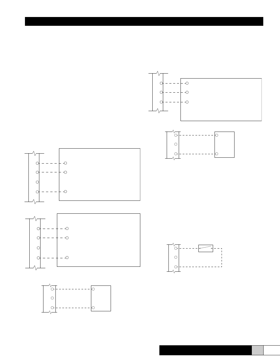
3. Limit Input - Unit can accept any sensor input as specified
above.
a. VDC sensor input (See Fig.16).
b. mADC sensor input (See Fig. 17).
External Off Switch
Should a field installed remote off switch be required, follow
the wiring diagram below (See Fig. 18). Be sure to remove the
jumper wire between poles 1 and 3 on “Controls Terminal Strip.”
The remote off switch is to be wired between poles 1 and 3. This
switch will override the unit on/off switch to turn the unit off only,
it will not restart the unit. The unit must be turn back on by the
unit on/off switch.
FIGURE 14B
HED3VSX
Duct
Sensor
(EST-1600)
PWR
RH (0-10 vdc Output)
GND
4
5
6
7
HEW3VSX
Wall
Sensor
(EST-1601)
PWR
RH (0-10 vdc Output)
GND
4
5
6
7
FIGURE 14A
7
8
9
PWR
GND
RH (0 -10 vdc Output)
HED3VSX
Duct
Sensor
(EST-1600)
FIGURE 16