K-Patents PR-01-S User Manual
Page 11
INSTRUCTION MANUAL FOR K-PATENTS PR-01-S (-AX/FM/CS)
DOCUMENT/REVISION No. INM 1/14
Effective: May 15, 2009
9
2.5. THE INDICATING TRANSMITTER
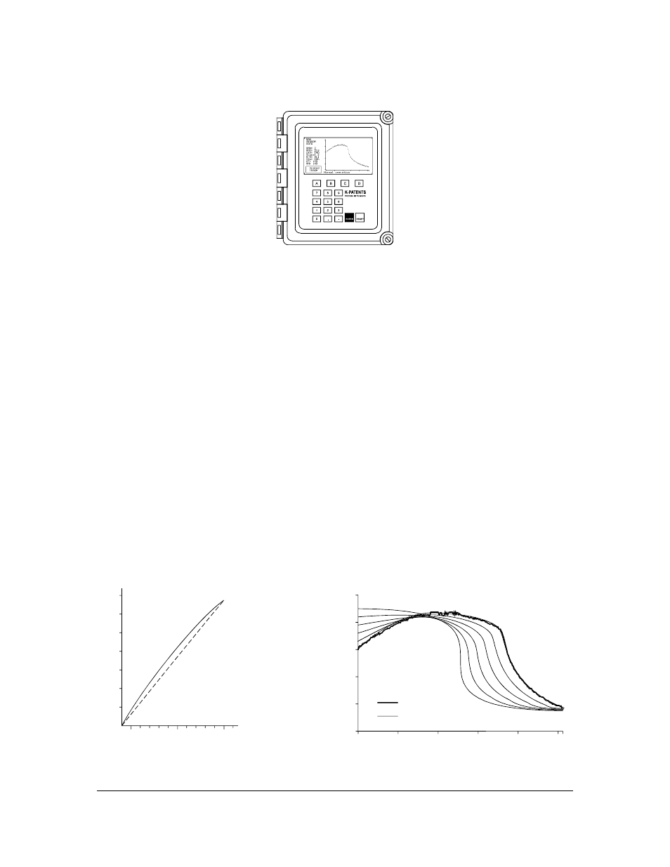
Figure 2.50
The Indicating transmitter (IT-R).
The Indicating transmitter IT-R (Figure 2.50) receives a serial signal from the Sensor describing the optical
image and also giving the process temperature. The microprocessor system displays the optical image
(Figure 2.72) and implements an image analyzing algorithm (Figure 2.52), which identifies the exact
position of the shadow edge shown in Figure 2.41.
The Indicating transmitter contains a power supply, a microprocessor system and a front panel with a
Liquid Crystal Display (LCD) and a Keyboard. The output signals are a 4-20 mA concentration signal and
a Serial output signal, RS232 or RS485 alternatively.
There are also two built-in signal relays on the power supply card inside the Indicating transmitter. These
two signal relays can be configured to any relay function, except to preconditioning or wash control
(described in Section 9.2). Configurations are made from the main calibration menu, see Figure 2.61. Note
the default setting for the built-in signal relay 1 is No Malfunction and for the relay 2 Internal humidity
above 50%. A closed contact on the relay 1 indicates that the instrument works properly. It is
recommended to use this relay for alarm purpose in a control system.
The Indicating transmitter also accepts 4 input switch closures for signal HOLD or scale selection. A serial
bus connects the Indicating transmitter to the external units such as Relay Unit (See Chapter 9) or External
Output Unit (Section 10.1).
Unauthorized access can be prevented: Knockout padlock provisions are included in both cover latches.
For password protection, see Section 2.11.
The microprocessor system linearizes the concentration reading, like in the example Figure 2.51, and
performs an automatic temperature compensation.
10
20
30
40
50
60
70
1.35
1.40
1.45
R.I.
BRIX
Figure 2.51
BRIX diagram.
Raw data
Curve fitted to the data
Figure 2.52
Image analyzing algorithm.