K-Patents PR-01-S User Manual
Page 86
INSTRUCTION MANUAL FOR K-PATENTS PR-01-S (-AX/FM/CS)
DOCUMENT/REVISION No. INM 1/14
Effective: May 15, 2009
84
CABLE FITTINGS:
The cable fittings are delivered as one of two alternatives:
US:
½ NPT-TYPE ST-1 conduit hubs: 4 pcs; PR-7080, 1 pc; -WR
European:
M20x1.5 metric cable glands: 4 pcs; PR-7080, 2 pcs; -WR
Note:
Seal all unused fittings with blind washers.
Each relay has one switch contact, for max 250 V AC, max 3 A. The Relay Card has also two monitoring
functions with two LEDs, See Figure 9.30 a, b:
a. The green LED L5 is lit, if the regulated 5 V supply to the processor is within limits 4.7 - 5.4 V and
the processor operates correctly. Note that the 24 V supply from the serial bus has to be checked with
a Volt-meter.
b. The red LED L6 is lit, if correct serial data are missing (but the processor operates correctly).
Both checks have to be OK, otherwise all relays will go into OFF state.
9.1. CONNECTIONS
The Relay Card is connected to the serial bus for PR-7080 and to the plug connector P2 on the power
supply card for wash control relay unit -WR, see Figure 3.62. The relay contacts go to the connector strip,
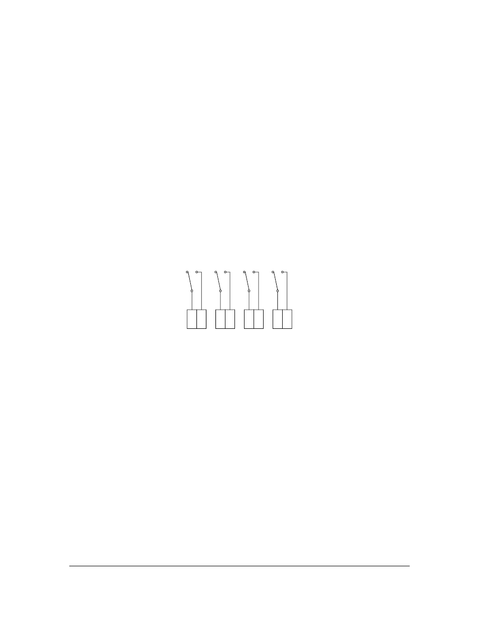
Figure 9.10.
A
B
C
D
44
46
48
50
45
47
49
51
Figure 9.10
PR-7080 Relay output connections. In wash control relay unit-WR only A and B
available.
9.2. RELAY UNIT CONFIGURATION
The relay functions and the wash timer settings can be seen from the Indicating transmitter. Press the key
sequence Display/System configuration/Relay configuration or Wash times.
– The relay functions can be reprogrammed any time from the calibration menu:
– Program a relay by the following steps:
– Press Calibrate/Parameters/Relays. Select the relay (A,B,C,D) to be programmed. Note! Only Relays
A and B are visible for Wash control relay unit-WR.
– For built in signal relays select: Relay 1 or Relay 2.