K-Patents PR-01-S User Manual
Page 40
INSTRUCTION MANUAL FOR K-PATENTS PR-01-S (-AX/FM/CS)
DOCUMENT/REVISION No. INM 1/14
Effective: May 15, 2009
38
5.5. MECHANICAL ZERO ADJUSTMENT
A mechanical zero adjustment can be made within the limits given in section 5.6. It is possible to make a
zero adjustment with the sensor in-line. For mechanical zero adjustment, remove the Image detector
module according to the instructions in Section 6.8.
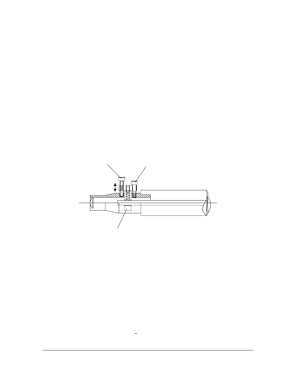
Near the tip of the Image detector module (Figure 5.50) there is a fiber optics holder (C) and two
adjustment screws. The two screws work against each other in a push-and-pull configuration. The locking
screw (A) pushes the holder inwards and the adjusting screw (B) pulls the holder outwards. A combined
push-and-pull force locks the holder.
To adjust, first loosen the locking screw (A) carefully. Then adjust the position of the fiber optics holder.
To increase the TEST reading and measure higher concentrations, turn the adjusting screw clockwise. To
decrease the test reading and measure lower concentrations, turn the adjusting screw counterclockwise.
When the position of the fiber optics holder (C) is correct, lock it into place by tightening the locking
screw (A) gently. Be careful not to bend the T-shaped holder (C) by forcing the locking screw too far in.
The visible part of the holder should always be in horizontal position.
Note: After the mechanical zero adjustment, check the optical image, see Section 6.5.
Warning: If the sensor cover is removed, ambient light disturbs the CCD signal.
C=fiber optics holder
B=adjusting screw
A=locking screw
Figure 5.50
Mechanical zero adjustment
5.6. SENSOR RANGEABILITY
The Sensor is made in two versions: Probe tip angle is either 50 degrees or 57 degrees. The value is
stamped on the probe tip.
The rangeability of the two sensor versions is described in Figure 5.60. The shaded area shows the span for
a typical mechanical zero setting. By mechanical zero adjustment (Section 5.5) the shaded area can be
moved right (holder moved outwards) or left within the borders of the rectangle. E.g. The 57 degree
version can measure up to RI 1.530.
If the desired measurement range cannot be achieved with the sensor version in use, then the sensor has to
be exchanged.
The standard span in Figure 5.60 is based on an objective lens focal length f=18. A wider span multiplied
by 1.8 (f=10) is available, with an accuracy of + 0.0003 R.I.