Eprom – K-Patents PR-01-S User Manual
Page 56
INSTRUCTION MANUAL FOR K-PATENTS PR-01-S (-AX/FM/CS)
DOCUMENT/REVISION No. INM 1/14
Effective: May 15, 2009
54
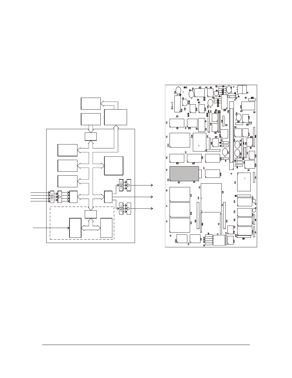
Processor card
The function of the Processor card is described by the block diagram Figure 6.42 and the component layout
Figure 6.43.
When measuring voltages on the Processor card it is important to remember that some parts are
galvanically separated from each other, see Figure 6.42. It is essential to use the right ground for
measurement.
DISPLAY
KEYBOARD
DISPLAY
CONTROLLER
CARD
CPU
80C186
SRAM
CPU
87C51
4-20 mA
OUTPUT
SERIAL
BUS
SERIAL
OUTPUT
RS-485/232
SENSOR
INTERFACE
SENSOR
DATA
SWITCHES
PROCESSOR
CARD
SRAM
EPROM
EEPROM
EPROM
Figure 6.42.
Processor card block diagram.
Figure 6.43.
Processor card layout
Diagnostic LEDs
Two LEDs on the Processor card indicate the CPU (80C186) activity:
LED D3 is lit when the processor is running
LED D4 is lit during interrupt service
Both LEDs should show a blinking light if the processor is working normally. Four rhythms with different
intervals are overlapping: 10 ms clock, 150 ms new sensor data, 800 ms new value calculation, 1 s timer
count. The most obvious rhythm is thy 800 ms one; first a short D4 blink, then a 200 ms D3 flash.