K-Patents PR-01-S User Manual
Page 29
INSTRUCTION MANUAL FOR K-PATENTS PR-01-S (-AX/FM/CS)
DOCUMENT/REVISION No. INM 1/14
Effective: May 15, 2009
27
Serial output RS-232/RS-485:
Terminals 15-18 and Plug connector P3, see Section 3.7.
Serial bus:
Terminals 8-14 provide connection to K-Patents accessory units, like the Relay unit (Chapter 9) and
External Output Unit (Section 10.1). The same type of cable is used as for the interconnecting cable to the
sensor specified in Section 2.2.
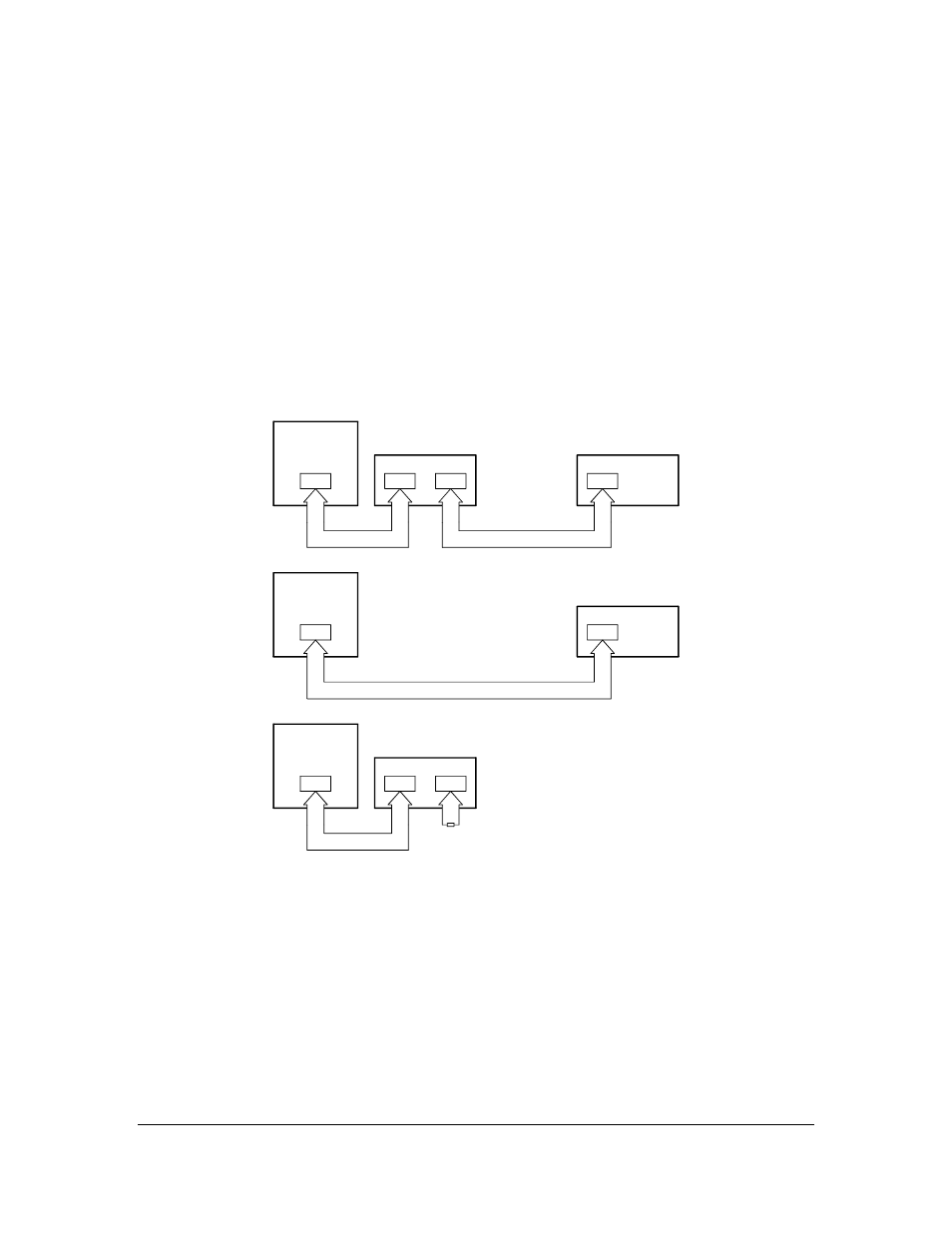
The terminals 8-14 are connected to the same numbers in the external units. Connect the external units in a
chain beginning from the Indicating transmitter and ending at the Relay unit (Figure 3.62). For an
intermediate unit (e.g. External output unit), the Serial bus input is terminals 8-14 /A and output 8-14/B. If
there is no Relay Unit to complete the chain, connect a 120 Ohm resistor over the terminals 8/B and 9/B at
the last unit.
Note: The current loop of the Serial bus must always be closed, by a Relay Unit or the 120 Ohm resistor.
Indicating
transmitter
Indicating
transmitter
Indicating
transmitter
8-14
8-14
8-14
8-14
8-14
8-14
8-14
8-14
8-9
A
A
B
B
External output unit
External output unit
Relay unit
Relay unit
120
Ohm
Figure 3.62
Serial bus connections.