K-Patents PR-01-S User Manual
Page 30
INSTRUCTION MANUAL FOR K-PATENTS PR-01-S (-AX/FM/CS)
DOCUMENT/REVISION No. INM 1/14
Effective: May 15, 2009
28
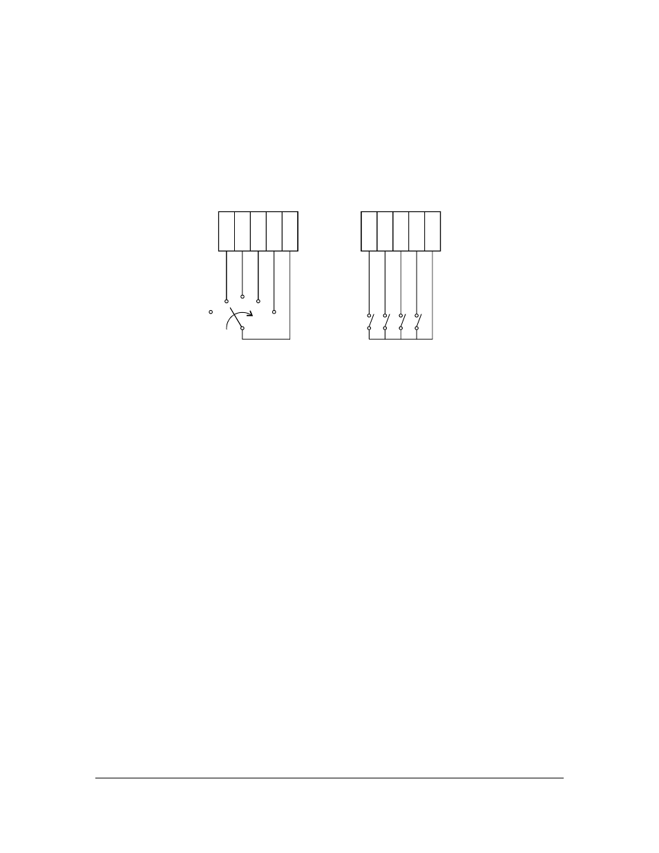
Input switches:
Altogether four input switches A, B, C and D (Figure 3.63) can be connected: Terminals 27-A, 28-B, 29-C,
30-D, 31-Common. The switches may be separate, or together in one rotary switch. Input switches can be
configured through software, Section 2.8.
A 5V voltage is provided over each switch. The switch terminals are all galvanically isolated from ground
and from the rest of the electronics.
27
27
28
28
29
29
30
30
31
31
SWITCHES
SWITCHES
B C D
A
D
C
B
A
Figure 3.63
Connections to input switches.
Built-in signal relays:
There are also two built-in signal relays on the power supply card inside the Indicating transmitter. These
two signal relays can be configured to any relay function, except to preconditioning or wash control
(described in Section 9.2). Configurations are made from the main calibration menu, see Figure 2.61. Note
the default setting for the built-in signal relay 1 is No Malfunction and for the relay 2 Internal humidity
above 50%. A closed contact on the relay 1 indicates that the instrument works properly. It is
recommended to use this relay for alarm purpose in a control system.
3.7. SERIAL OUTPUT
A remote display unit, a computer, or a terminal can be connected to the PR-01-S serial output terminals.
In the Indicating transmitter either RS-232 or RS-485 interface may be used.
The output measurement results are sent in ASCII code (ISO 646, CCITT V.3) using a standard
asynchronous interface. The output consists of fixed-length text records. A record is sent for every
measurement interval (800 ms).
RS-232: Conforms to the EIA RS-232-C and CCITT V.24 standards. The signals are available at plug
terminal P3. Cable diagrams are shown in figure 3.70 (for modems) and figure 3.71 (for computers). Both
25-pin and 9-pin D-shell connector pin numbers are given. If the IT-R is to be connected to a computer,
connections 4-5 and 6-8-20 (see figure 3.70) may be omitted in most cases. Note: RS-232-C specifies a
maximum cable length of 15 m.
RS-485: The physical interface conforms to the EIA RS-485. The cable should be a shielded twisted pair.
The RS-485 signals are available at P3 (DAT- and DAT+ in figure 3.70) or strip terminals 15-18. For a
shielded cable connection (recommended), see figure 3.61. K-Patents recommends a cable length not
exceeding 200 m.