Lynx Studio LT-FW User Manual
Page 22
Page 22 of 43
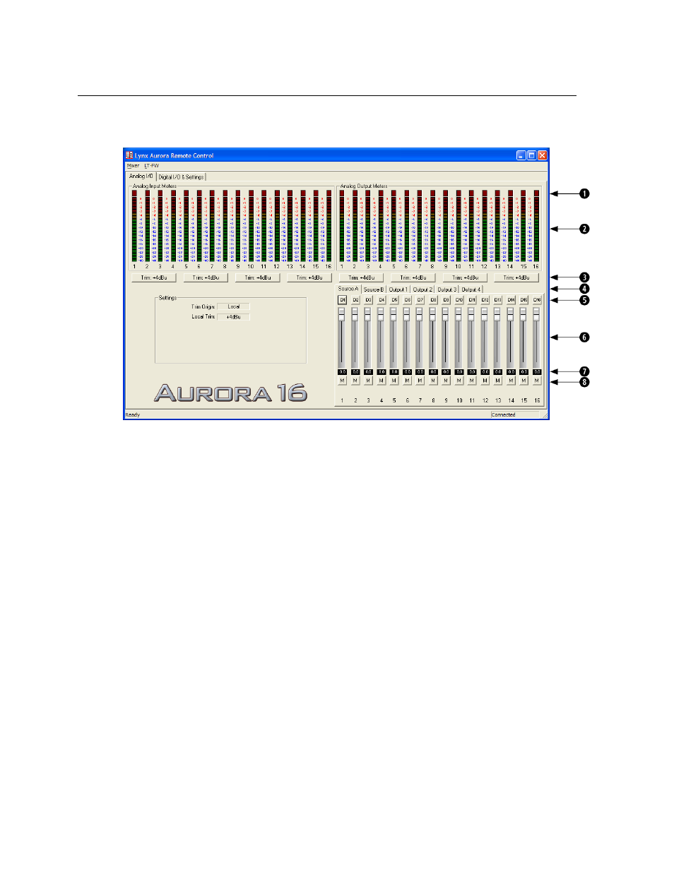
7.3.1 Analog I/O Page
This page is viewable by clicking the “Analog I/O” Tab in the top left corner of the Aurora
Remote Control application.
q
These indicators will illuminate when three consecutive full-scale samples are
detected on the Aurora Analog Inputs and Outputs or when a summing overrun
occurs on the Aurora Analog Outputs. The indicator will remain illuminated for
250ms.
w
These meters display the instantaneous peak level of audio being sent to the Aurora
Analog Inputs and Outputs.
e
These buttons allow the Analog input or output trims to be set. Each button allows
groups of fours channels to be toggled between +4dBu (the default) and -10dBV.
r
These tabs allow monitor source groups to be selected for the Analog Outputs when
Remote Routing is utilized. The Aurora can be set for global routing (i.e. AES In
routes to Analog Out) or Remote Routing. With Remote Routing up to two sources
(Source A and Source B) can be established for each output. Analog Outputs 1-4 have
16 additional monitor sources (Sources C – R), which can be accessed from the
Output 1-4 tabs. For these custom monitor sources to be active, the TO ANALOG
OUT switch on the Digital I/O & Settings page must be set to “Remote”. In this state
all three LEDs for the TO ANALOG OUT button on the Aurora front panel will be
illuminated.
t
These buttons allow individual monitor sources to be selected for each analog output
when using Remote Routing. Clicking a button allows selection of any Analog,
Digital or LSLOT input source. Holding down the CTRL key while selecting a source
causes the remaining channels to be set sequentially (i.e. if you select LSLOT In 1 as