Lynx Studio LT-USB User Manual
Page 8
5 Inst
Please in
1. Remo
large
cover
2. Befor
that c
Slide
If you
switc
3. Remo
moun
after
tallation P
nsure that the
ove the AC p
screws plus
r on.
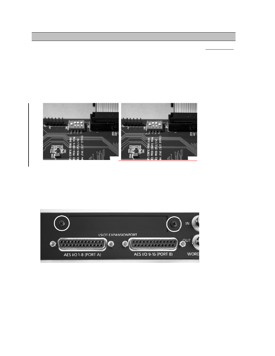
re installing
corrects the c
switch 4 (la
u are updatin
ches, please c
ove the LSL
nting screws
installation.
Procedures
e Aurora ha
power cord a
s one small s
the LT-USB
current draw
abeled W4 o
ng an older A
call Lynx Te
LOT Expansi
. Set these tw
P
s
s firmware 2
and take the
screw near th
B card, you m
w for an Auro
n PCB) of S
Aurora that h
echnical Sup
ion Port cove
wo screws a
age 8 of 45
24 or above
top cover of
he center of t
must change
ora with an L
SW1 to the O
has jumper p
pport for inst
er above the
side, as they
before proce
ff of the Aur
the front fac
e a dipswitch
LT-USB
OFF position
pins at JP6, i
tructions.
e AES I/O Po
y will be used
eeding. See
rora. There a
ceplate that h
h setting on t
n (towards ba
instead of th
orts by remo
d to secure t
Section 2.2.3
are seven
holds the top
the Aurora
ack panel).
he W4
oving the two
the LT-USB
3
p
o