REMKO WKF 120 Duo User Manual
Page 11
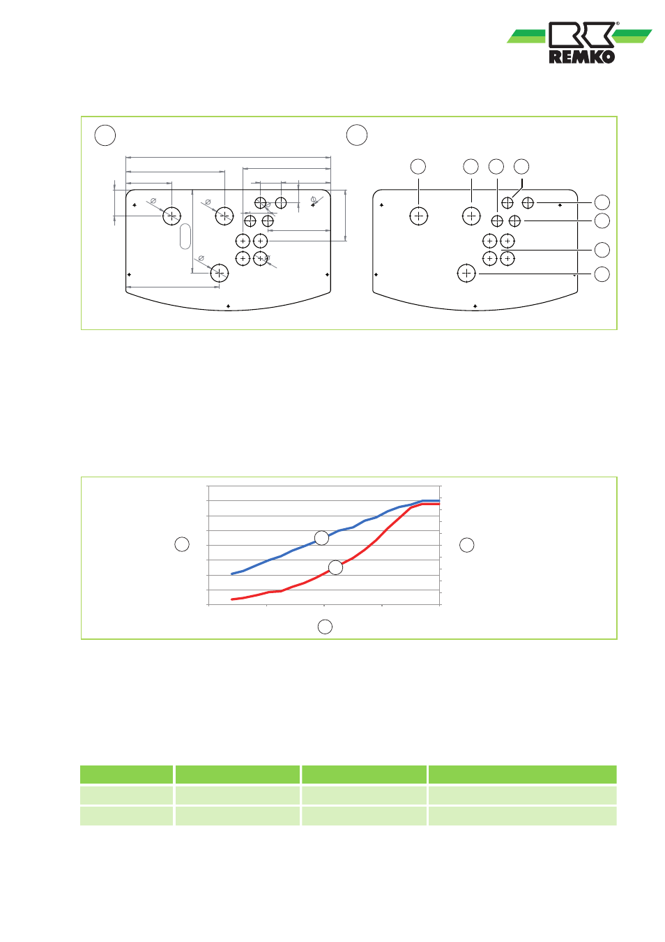
Arrangement of the pipe sockets and designations on the pipe connections
A
B
285
320
157
337
90
45
70
170
60
215
300
175
37
6
60
60
60
47
700
1
2
3
4
5
6
7
8
Fig. 3: Arrangement of the pipe sockets and designations on the pipe connections WKF 120/180 Duo
A:
Pipe connection arrangement
B:
Designations of the pipe connections
1:
Heat pump inlet, 1 1/2"
2:
Heat pump return, 1 1/2"
3:
Refrigerant heat gas pipe, Outdoor unit A 5/8"
4:
Refrigerant liquid pipe, Outdoor unit B 3/8"
5:
Refrigerant liquid pipe, Outdoor unit A 3/8"
6:
Refrigerant heat gas pipe, Outdoor unit B 5/8"
7:
Cable feedthrough
8:
Safety assembly
2.4
Pump-characteristic curves, indoor module charging pump
0
5
10
15
20
25
30
35
40
45
50
0
20
40
60
80
100
120
140
160
20
40
60
80
100
[l/
m
in
]
[W]
[%]
2
1
3
A
B
Fig. 4: Circulation pump Grundfoss UPML 25-105 180 PWM - power range
1:
Power consumption [W]
2:
Volume flow [l/mim]
3:
Activation [%]
A:
Characteristic curve volume flow [l/mim]
B:
Characteristic curve power consumption [W]
External control via analogical-in PWM-signal
Tolerances of each curve according to EN 1151-1:2006
Level
Output [W]
Current [A]
Motor protection
min.
7
0,07
Rotor current-proof
max.
136
1,03
Rotor current-proof
11