2 emergency-heat operation, Emergency-heat operation – REMKO WKF 120 Duo User Manual
Page 53
13.2
Emergency-heat operation
Should you experience faults with the Smart Con-
trol or with the outdoor module during operation of
your heat pump system, it is possible to activate a
manual emergency-heat operation. To do so, the
electric heating coil, internal primary pump, and if
necessary the circulation pumps heating cycle
must be switched on manually.
To activate emergency-heat operation if the Smart
Control fails, proceed as follows:
1.
Remove the top front panel.
2.
Set the black knob of the electrical terminal
box (located on the left-hand side) for the
auxiliary heater to "position 2".
3.
Set the thermostat on the electrical terminal
box of the auxiliary heater to the desired tem-
perature, e.g. floor heating 35°C, heating ele-
ment 50°C.
4.
Turn the rotary switch on the primary pump
(Wilo) clockwise to roughly the "5 o'clock"
position.
5.
If you are using external heating cycle groups
(pumps), they must also be provided with a
separate power supply.
6.
If you are using external heating cycle groups
(pumps), HGU or HGM from Remko, you
should also set the rotating wheel on the
front of the pump to the "5 o'clock" position.
7.
Remove the servo motor of the three-way
changeover valve by pulling out the safety
split pin between motor and valve body (see
separate "Three-way changeover valve"
operating instructions).
8.
Pull the motor away from the valve body.
9.
Turn the cylindrical ball valve in the direction
of Outlet B using the round side (floor heating
side or heating element).
To switch to providing hot water, proceed as fol-
lows:
1.
Turn the cylindrical ball valve in the direction
of Outlet A using the round side (domestic
water storage tank).
2.
Set the thermostat on the electrical terminal
box of the auxiliary heater to the desired tem-
perature, e.g. 50°C.
The following directions of flow must be realised
manually:
Valve connection B -- Heating
Valve connection A -- Domestic water storage tank
The respective operating modes must be
switched manually!
To activate emergency-heat operation if the out-
door unit fails, proceed as follows:
1.
In the menu of the Smart Control, go to the
………… screen.
2.
Set the bivalence point of the controller
above the unit's heating limit.
3.
The electric heating element is then acti-
vated.
4.
Check the set temperature on the thermostat
of the electric heating element.
5.
If necessary set it above the max. desired
temperature (HW target temperature), e.g. if
HW target temperature = 45°C, then heating
element = 50°C.
6.
The Smart Control takes full control of heat
regulation and the activation of the heating
element.
1
2
3
4
5
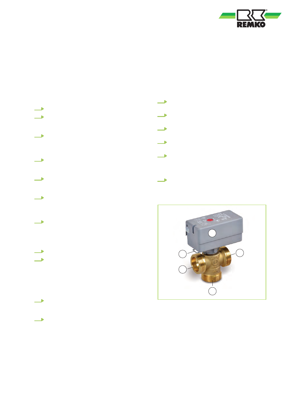
Fig. 47: 3-way-changeover valve
1: Servo motor
2: Safety split pin
3: Connection A, domestic water storage tank
4: Connection B, heating
5: Connection AB
53