4 setup, installation of the outdoor unit, Setup, installation of the outdoor unit – REMKO WKF 120 Duo User Manual
Page 31
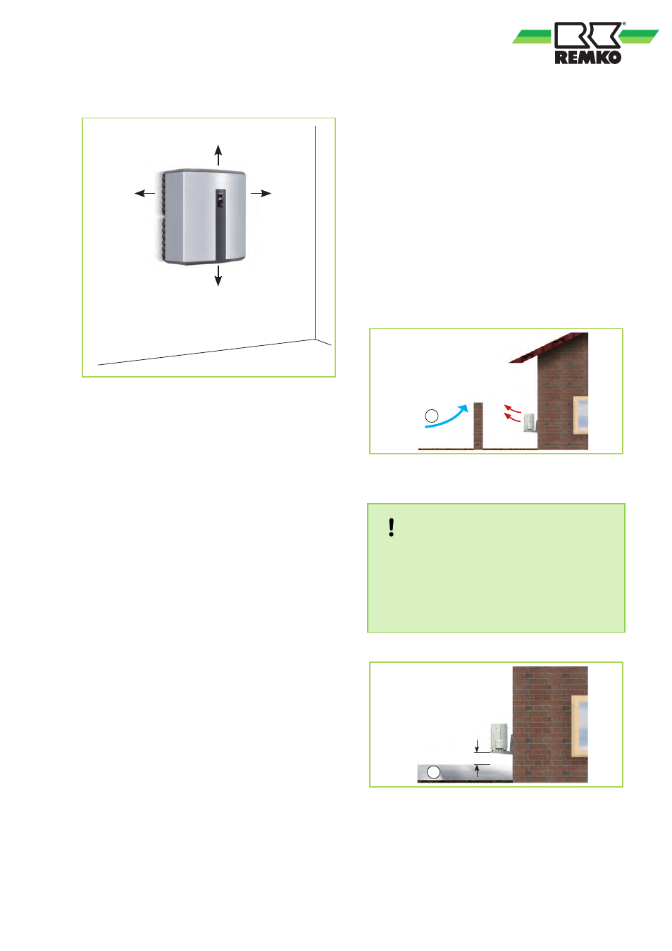
Minimum clearances for the indoor unit
500
300
300
150
Fig. 30: Minimum clearances for the indoor unit in
mm
4.4
Setup, installation of the
outdoor unit
Outdoor unit installation location
n
The unit may only be attached to a load-
bearing structure or wall. Make sure that the
outdoor unit is only installed vertically. The
installation site should be well ventilated.
n
To minimise noise, the preferred mounting
method is to use a floor bracket with vibration
dampers, placed a significant distance from
sound-reflecting walls.
n
The minimum clearances specified on the next
page should be maintained when carrying out
the installation. These minimum clearances
serve to ensure unrestricted air intake and
exhaust. Additionally, there must be adequate
space available for installation, maintenance
and repair.
n
If the outdoor unit is erected in an area of
strong winds, then the unit must be protected
against them (Fig. 31). The snow line is to be
observed during installation (Fig. 32).
n
The outdoor unit must always be installed on
vibration dampers. Vibration dampers prevent
the transmission of vibrations through the floor
or walls.
n
A heated, condensate catch-pan ensures that
condensation from the pan can drain off.
Ensure that the condensate is prevented from
freezing so that it can drain off (gravel,
drainage). The Water Ecology Act is to be
observed.
n
If there is insufficient space under the device
for the refrigerant piping, then the pre-cut
recesses can be removed from the lower cover
panel and the pipes guided through these
openings.
n
During installation, add about 20 cm to the
expected snow depth to guarantee unimpeded
intake and exhaust of outdoor air year round
n
The installation site of the outdoor unit should
be agreed together with the operator primarily
so that operating noise is minimised and not in
terms of "short routes". This is because, thanks
to the split-design technology, there are a great
deal of different installation options with almost
identical efficiency available.
1
Fig. 31: Protection from wind
1: Wind
NOTICE!
The site for the outdoor unit must be selected
so that machinery noise that occurs disturbs
neither the residents nor the facility operator.
Observe the TA-noise specifications as well as
the table containing the drawings relating to
sound pressure levels.
20 cm
1
Fig. 32: Protection from snow
1: Snow
31