Remko wkf duo, Ib ab – REMKO WKF 120 Duo User Manual
Page 28
Advertising
IB
AB
STL
KML
NAM
KA1
AM1
VEN
AM2
VEN
KA1
NAM
VEN
VEN
STL
KML
IM
NIM
NZH
KA2
VHZ
GRL
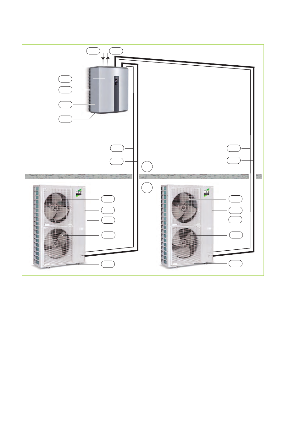
Fig. 27: WKF 180 Duo system layout
AB:
Outdoor area
IB:
Indoor area
AM1,2:
WKF 180 Duo outdoor unit
IM:
WKF 180 Duo indoor unit
GRL:
Common return pipe
KA1:
Condensate drain, OU (must be designed
to be frost proof!)
KA2:
Condensate drain, IU
KML:
Refrigerant piping
3
/
8
" and
5
/
8
"
NAM:
Power supply, OU = 400V / 3~ / 50Hz
3x16A (e.g. 5x1.5 mm
2
)
NIM:
Power supply, IU = 230V / 1~ / 50Hz
16A (e.g. 3x1.5 mm
2
)
NZH:
Power supply for auxiliary heater
(e.g. 5x2.5 mm
2
)
STL:
Control line (e.g. 2x1 mm
2
)
VEN:
Fan
VHZ:
Inlet for heating
REMKO WKF Duo
28
Advertising
This manual is related to the following products: