3 installation and connection (for base station), Connection diagram, Procedure – Alinco DR-SR8 User Manual
Page 15
13
Chapter 1 Getting Started
1.3 Installation and Connection (For Base Station)
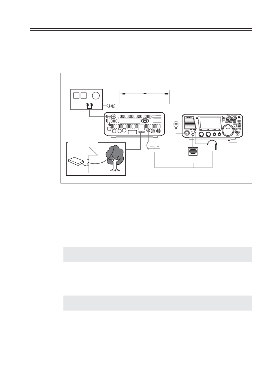
Connection Diagram
This diagram shows the connections for a base station.
Microphone
Speaker
Headphone
Stand
Key
optional
HF band antenna
13.8V DC regulated
power supply
EDX-2 (optional)
Long-wire
antenna
Procedure
1. Connecting an antenna and ground cable
• Antenna connection
Use a properly-adjusted (low SWR) antenna to obtain optimum performance from the
transceiver. A 50 ohm impedance coaxial with PL-259 connector is required for this
connection.
NOTE:
It is recommended to use an optional automatic antenna tuner (EDX-2) for proper
antenna matching.
• Ground connection
To prevent electric shock hazard and audio interference with other electronic appliances,
bury a copper rod or plate under the ground and connect it to the transceiver GND
terminal. Use a heavy gauge, short cable for this connection.
IMPORTANT:
Do not ground the equipment on gas pipes, electrical conduits, or plastic
water pipes.