Rear panel, S5800-56c panel views, Front panel – H3C Technologies H3C S5800 Series Switches User Manual
Page 17
7
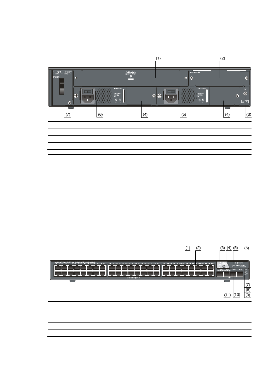
Rear panel
Figure 2 S5800-60C-PWR rear panel
(1) OAP card slot
(2) PoE module slot
(3) Grounding screw
(4) Filler modules
(5) Power module slot 1
(6) Power module slot 2
(7) Hot swappable fan tray
NOTE:
•
The S5800-60C-PWR switch comes with power module slot 1 empty and power module slot 2 covered
by a filler panel. You can install one or two power modules for the switch as needed. In this figure, two
PSR300-12A AC power modules are installed in the slots.
•
This switch also comes with the PoE module slot and the OAP card slot covered by filler panels.
S5800-56C panel views
Front panel
Figure 3 S5800-56C front panel
(1) 10/100/1000Base-T auto-sensing Ethernet port
(2) 10/100/1000Base-T Ethernet port LED
(3) Seven-segment LED
(4) Port mode LED
(5) SFP+ port LED
(6) Logo plate (A console port and a USB port are under this logo plate)
(7) System status LED (SYS)
(8) RPS status LED (RPS)
(9) Interface card status LED (SLOT1)
(10) SFP+ port
(11) Port LED mode switching button
To use the console port and USB port, open the logo plate.