Planning the cabling scheme – H3C Technologies H3C S5800 Series Switches User Manual
Page 91
81
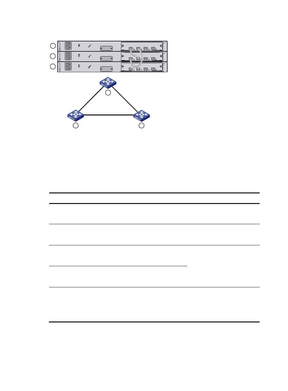
Figure 92 IRF fabric in ring topology
Identifying physical IRF ports on the member switches
Identify the physical IRF ports on the member switches according to your topology and connection
scheme.
shows the physical ports that can be used for IRF connection and the port use restrictions.
Table 34 Physical IRF port requirements
Switch chassis
Candidate physical IRF ports
Requirements
S5800-60C-PWR
Ports on the expansion interface cards on the
front panel
All physical ports of an IRF port must
be located on the same interface
card.
•
S5800-56C
•
S5800-56C-PWR
•
The four fixed SFP+ ports on the front panel
•
Ports on the expansion interface card on the
rear panel
All physical ports of an IRF port must
be located on the front panel or the
interface card on the rear panel.
•
S5800-32C
•
S5800-32C-PWR
•
The four fixed SFP+ ports on the front panel
•
Ports on the expansion interface card on the
rear panel
An IRF port can use physical ports
distributed on different cards.
S5800-32F
•
The four fixed SFP+ ports on the front panel
•
Ports on the expansion interface card on the
front panel
S5800-54S
The six fixed SFP+ ports (in two groups) on the
front panel:
•
SFP+ ports 49, 50, and 52 in one group
•
SFP+ ports 51, 53, and 54 in the other
group
All physical ports of an IRF port must
be in the same group.
Planning the cabling scheme
Use SFP+ cables, twisted pair cables, or SFP+ transceivers and fibers to connect the IRF member switches.
If the IRF member switches are far away from one another, choose the SFP+ transceiver modules with
1
2
3
1
2
3
IRF-port1
IRF-port2
IRF-port1
IRF-port1
IRF-port2
IRF-port2