Installing a power module – H3C Technologies H3C S5800 Series Switches User Manual
Page 61
51
To avoid damage to the device and bodily injury, always follow the power module installation and
.
Figure 47 Installation procedure
Figure 48 Removal procedure
Installing/Removing a power module (for the S5800-54S)
Installing a power module
To install an LSVM1AC650, LSVM1DC650, LSVM1AC300, or LSVM1DC300 power module into the
S5800-54S switch:
1.
Wear an ESD-preventive wrist strap and make sure it makes good skin contact and is well
grounded.
2.
Unpack the power module and check that the power module model is correct.
3.
Correctly orient the power module with the power module slot (see
of the module with one hand and support the module bottom with the other, and slide the module
slowly along the guide rails into the slot. The slot is foolproof. If you cannot insert the power module
into the slot, re-orient the power module rather than use excessive force to push it in.
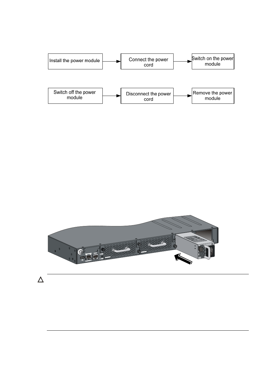
Figure 49 Install a power module
CAUTION:
•
Follow the forward inertia of the power module when inserting it into the chassis to ensure that the
power module has firm contact with the connectors on the backplane.
•
To prevent damage to the connectors inside the switch chassis, insert the power module gently. If you
encounter a hard resistance while inserting the power module, pull out the power module and insert it
again.
•
To ensure good ventilation of the switch, install a power filler module in the empty power module slot if
the switch is installed with only one power module, as shown in
.