Figure 29, Figure 30 – H3C Technologies H3C S5800 Series Switches User Manual
Page 48
Advertising
38
1.
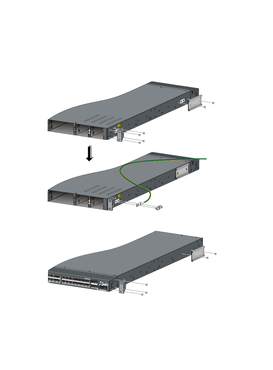
Select a grounding point.
2.
Unpack the grounding cable and grounding screws. (You can use the cable and screws for
connecting to the primary grounding point or auxiliary grounding point 1.)
3.
Align the two-hole grounding lug at one end of the cable with the grounding holes of the
grounding point, insert the grounding screws into the holes, and tighten the screws with a
screwdriver to fix the grounding lug to the chassis, as shown in
Figure 29 Attach the rear mounting brackets, chassis rails, and the grounding cable to the chassis
Figure 30 Attach the rear mounting brackets and the chassis rails to the chassis
Advertising