Connecting the lsvm1ac650/lsvm1ac300, R750-d, as shown in, Figure 71 – H3C Technologies H3C S5800 Series Switches User Manual
Page 75: Figure 72, T 2 in
65
NOTE:
Follow these guidelines when you use the RPS1000-A3 to supply power to the S5800-60C-PWR switch:
•
You must install the RPS1000-A3 with two power modules. With only one power module, the RPS might
enter the over-current protection state and stop supplying power.
•
Ensure that the two lines between the PSR750-D and the RPS1000-A3 are securely connected. Insecure
connection of either line can cause the affected power module to enter the over-current protection state
and stop supplying power to the switch.
•
You must connect the PSR750-D to the RPS1000-A3 by using the dedicated H3C power cable, and
correctly identify the positive (+) and negative (-) marks on the wires.
•
The RPS1000-A3 has eight outputs, and you can connect the PSR750-D only to OUTPUT1 and
OUTPUT2.
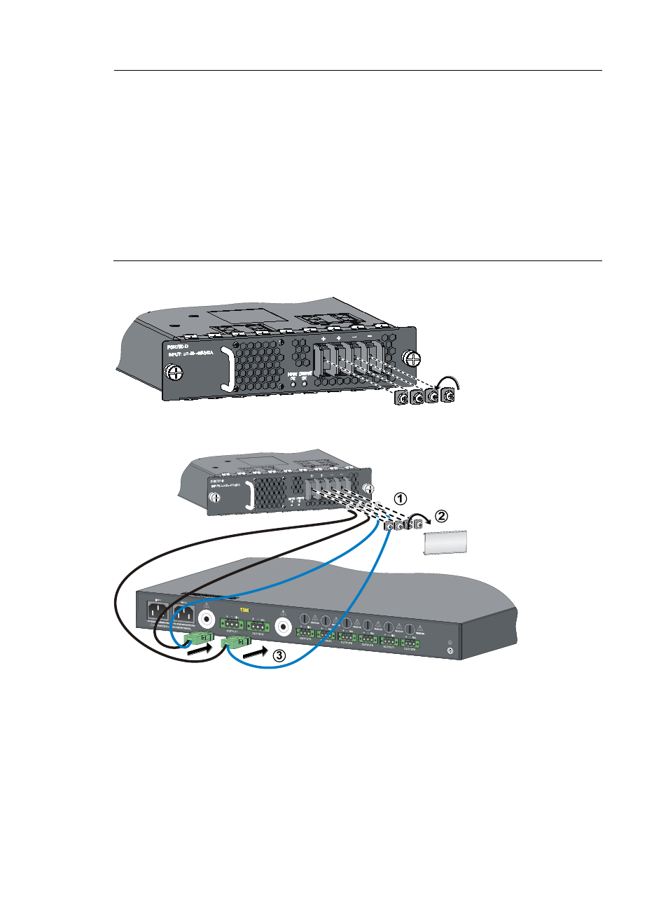
Figure 71 Remove the protective cover from the PSR750-D
Figure 72 Connect the PSR750-D to the RPS1000-A3
Connecting the LSVM1AC650/LSVM1AC300
1.
Insert the female connector of the AC power cord supplied with the power module into the
AC-input power receptacle of the power module.
2.
Use a cable tie to secure the power cord to the handle of the power module, as shown in
.
3.
Connect the other end of the power cord to an AC power outlet.