3 connecting the ethernet interface, 4 connecting the s0 output, Connecting the rs485 bus – KACO Powador 10.0 - 20.0 TL3 User Manual
Page 25
EN
Installing the inverter
Operating Instructions Powador 12.0 TL3-20.0 TL3
Page 25
Authorised electrician
7.3.3 Connecting the Ethernet interface
NOTE
The connection plug of an RJ45 cable is larger than the opening of an M25 cable fitting when it
is installed. For this reason, remove the sealing insert before installation and thread the Ethernet
cable outside of the cable fitting through the sealing insert.
NOTE
Use a suitable category 5 network cable. The maximum length of a network segment is 100 m.
Ensure that the cable is correctly assigned. The Ethernet connection of the inverter supports
auto-sensing. You can use both crossed and 1:1 protectively-wired Ethernet connection cables.
Connecting an Ethernet cable to the inverter
1. Loosen and remove the cover of the cable fitting (see Figure 13 on page 24).
2. Remove the sealing insert.
3. Thread the connection cable through the cover of the cable fitting and the sealing insert.
4. Insert the sealing insert into the cable fitting.
5. Connect the connection cable to the Ethernet interface (see Figure 13 on page 24).
6. Attach and tighten the cover of the cable fitting.
Connecting the inverter to the network
↻ Connect the Ethernet cable to the inverter.
↻ Configure the Ethernet interface in the configuration menu.
"
Connect the Ethernet cable to the network or a computer.
"
Configure the Ethernet settings and the web server in the Settings/Network menu.
7.3.4 Connecting the S0 output
7.3.5
An S0 pulse output is located on the communication board. Use this output to control accessories such as
a large display, for example. The pulse rate of the output is adjustable.
Connecting the S0 output
1. Unscrew the cable fitting (see Figure 13 on page 24).
2. Thread the connection cables through the cable fitting.
3. Attach the connection cables to the connection terminals.
4. Tighten the cable fitting.
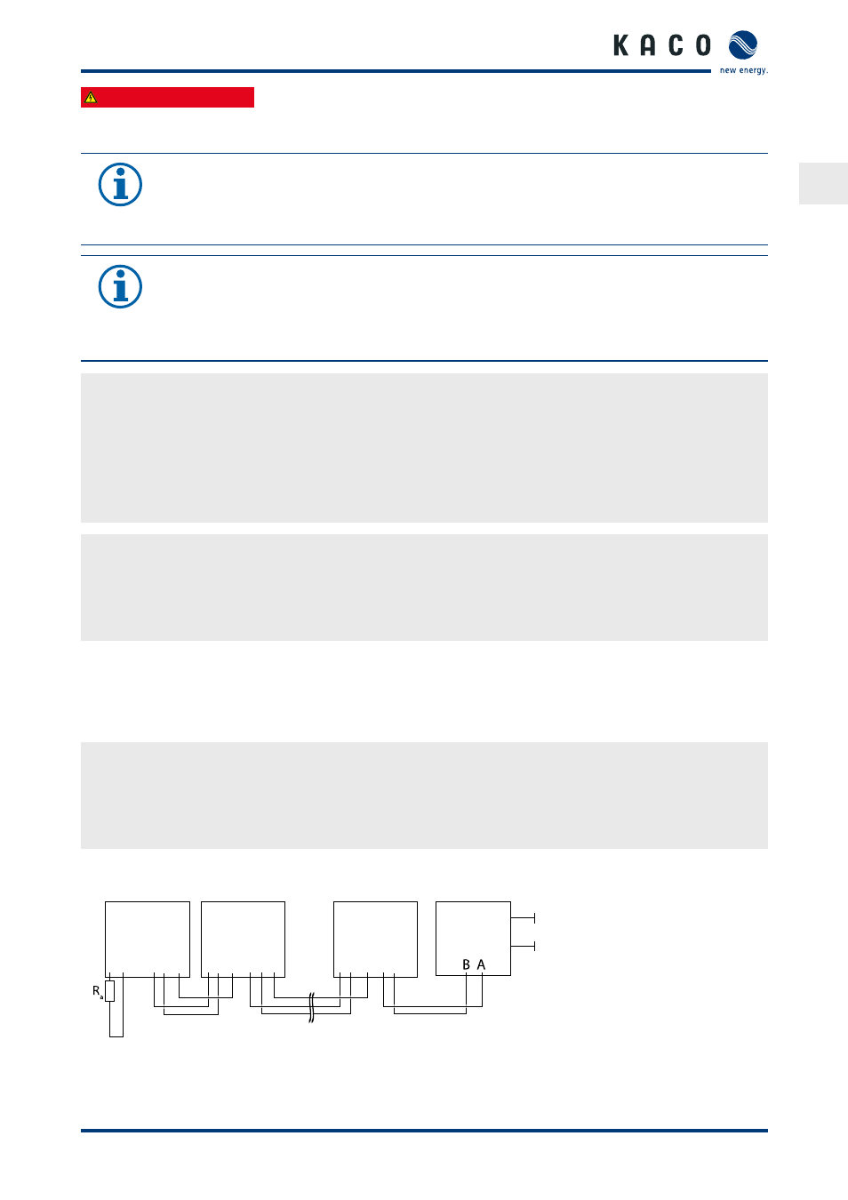
Connecting the RS485 bus
A B
GND
A B
GND
A B
GND
A B
GND
A B
GND
A B
GND
Powador
Wechselrichter
Endgerät
Powador
Wechselrichter
Powador
Wechselrichter
Daten-
logger
Kommunikation
230 VAC
Figure 14: RS485 interface wiring diagram