Sealing the connection area – KACO Powador 10.0 - 20.0 TL3 User Manual
Page 27
EN
Installing the inverter
Operating Instructions Powador 12.0 TL3-20.0 TL3
Page 27
Authorised electrician
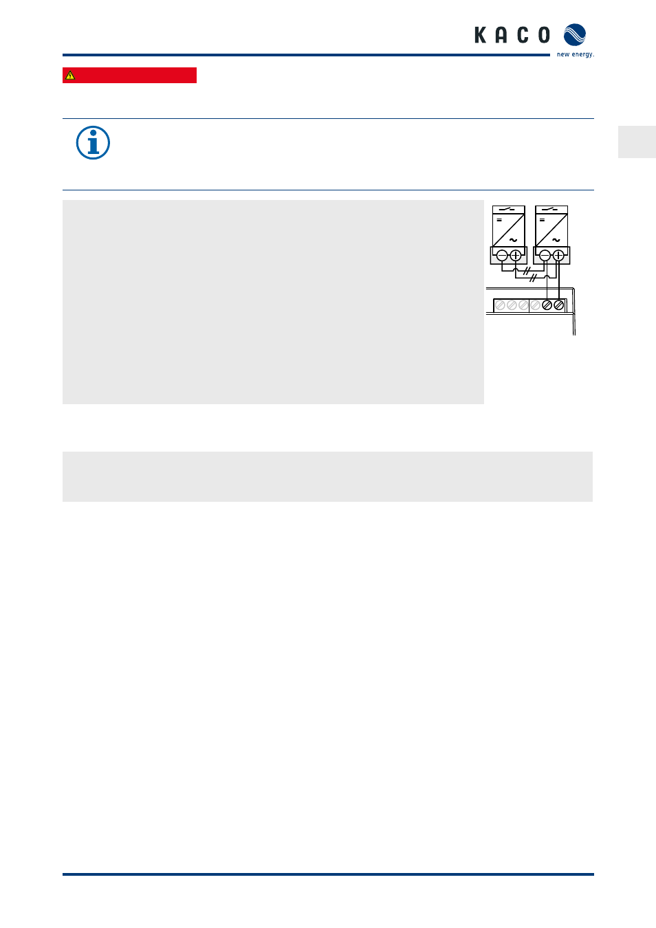
7.3.6 Connecting "Inverter off" digital input (optional)
NOTE
The Powador-protect digital output can only be used with suitable KACO inverters. When using
devices from other manufacturers or in combination with KACO inverters, bus coupler circuit-
breakers as a minimum must be used for shutting down devices from other manufacturers.
Connecting and activating "Inverter off" digital input
↻ Can only be used with suitable KACO inverters.
1. Unscrew the cable fitting.
2. Thread the connection cables through the cable fitting.
3. Connect wire A (+) to the terminal marked "EVU+" or “INV+” on the first inverter via the
"DO1" terminal of the Powador-protect.
4. Connect wire B (-) to the terminal marked "EVU-" or “INV-” on the first inverter via the
"GND" terminal of the Powador-protect.
5. Connect the other inverters to one another as follows:
–
wire A (+) to wire A (+) and wire B (-) to wire B (-).
6. Tighten the cable fitting.
7. After commissioning: Activate the support for the Powador protect in the parameter
menu under the "Powador-protect" menu item.
D01
GND
4
3
2
1
Figure 15: Powador-
protect
7.3.7
Sealing the connection area
1. The requirements of protection rating IP65 are met by closing the unused cable fittings with blind caps.
2. Place the connection cover on the connection area of the inverter.
3. Screw in the four Torx screws on the front side of the connection cover (blue).