KACO Powador 10.0 - 20.0 TL3 User Manual
Page 26
EN
EN
Installing the inverter
Page 26
Operating Instructions Powador 12.0 TL3-20.0 TL3
Authorised electrician
NOTE
Different manufacturers do not always interpret the standard on which the RS485 protocol is
based in the same way. Note that the wire designations (- and +) for wires A and B can vary between
manufacturers.
NOTE
Calculating efficiency by measuring the current and voltage values can lead to misleading results
due to the tolerances of the measurement devices. The sole purpose of these measured values is to
monitor the basic operation of the system.
Connecting the RS485 bus
"
Maximum length of the RS485 wiring: 1,200 m under optimal conditions.
"
Maximum number of connected bus devices: 31 inverters + 1 data monitoring unit
"
Use a twisted, shielded data cable.
Recommendation (using wire sleeves)
–
LI2YCYv (TP) black for laying cable outside and in the ground 2 x 2 x 0.5
–
LI2YCY (TP) grey for dry and moist indoor spaces 2 x 2 x 0.5
1. Unscrew the cable fitting (see Figure 13 on page 24).
2. Thread the connection cables through the cable fitting.
3. Connect the connection cables to the corresponding connection terminals (see Figure 13 on page 24).
4. Connect as follows to all inverters and to the Powador-proLOG as follows:
–
Wire A (-) with wire A (-) and
–
Wire B (+) with wire B (+) (see Figure 14 on page 25)
5. Tighten the cable fitting.
6. Activate the terminating resistor on the terminal unit.
7.3.5.1 Variant 1: Activating the terminating resistor via the menu
7. Open the menu.
8. Navigate to the „Settings“/“Interface“ menu entry.
9. Activate the terminating resistor via the „Bus termination” menu item.
10. Confirm with „OK“.
7.3.5.2 Variant
2: Activating the terminating resistor via DIP switches
Activate the terminating resistor in the inverter that represents the terminal unit within your wiring diagram.
NOTE
Always activate the RS485 terminating resistor in the terminal using DIP switch 2.
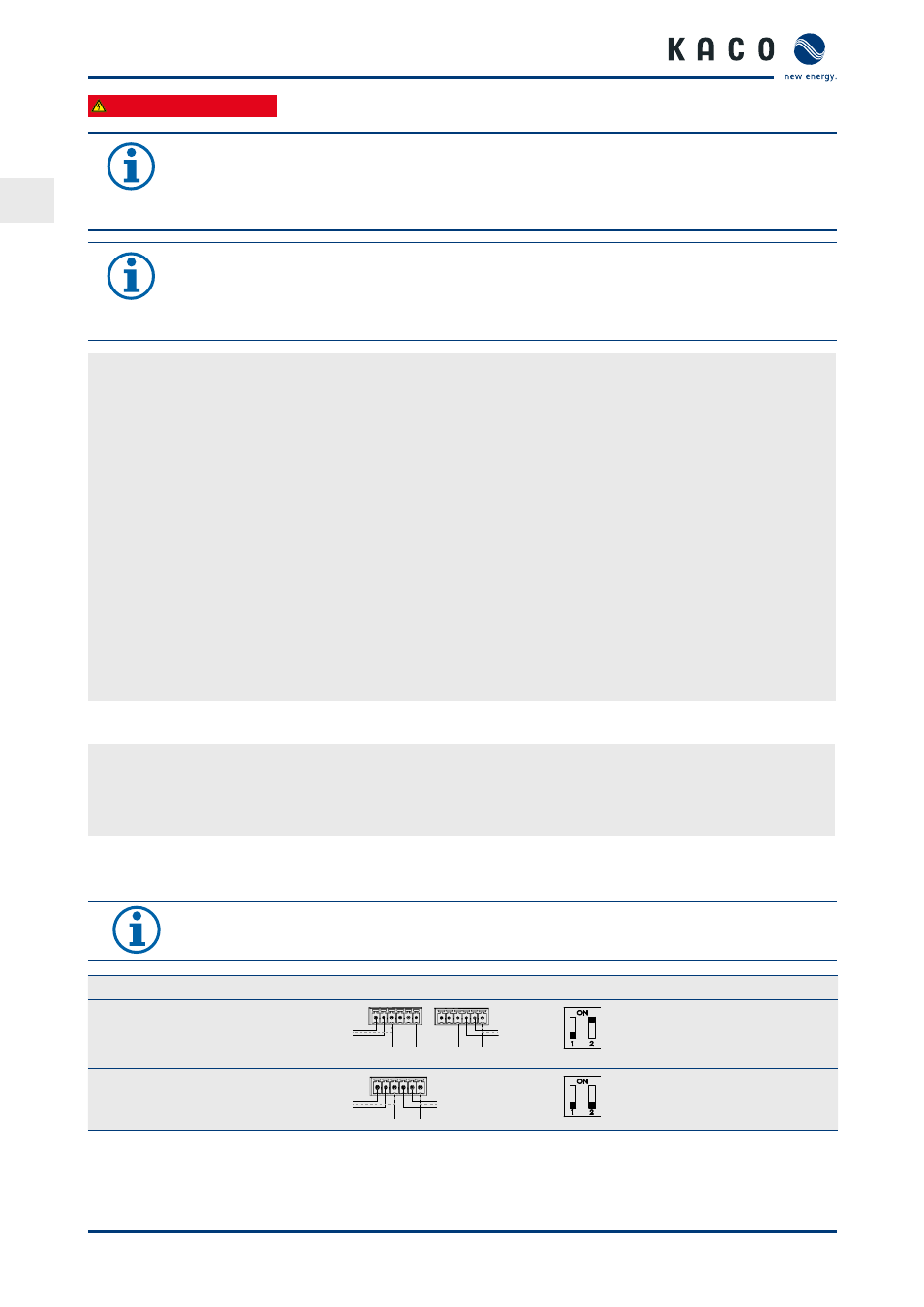
Connection samples
DIP switch
Switch 1
Switch 2
Inverter is the terminal:
"
Activate switch 2
B
A
B
A
GND GND
,
B
A
B
A
GND GND
OFF
ON
The inverter is not the terminal unit:
"
Deactivate switch 2
B
A
B
A
GND GND
OFF
OFF