KACO Powador 10.0 - 20.0 TL3 User Manual
Page 8
EN
EN
Description
Page 8
Operating Instructions Powador 12.0 TL3-20.0 TL3
Feed-in meter
The feed-in meter is specified and installed by the power supply company. Some power supply companies also
allow the installation of your own calibrated meters.
Selective main switch
If you have any questions about the selective main switch, contact your power supply company.
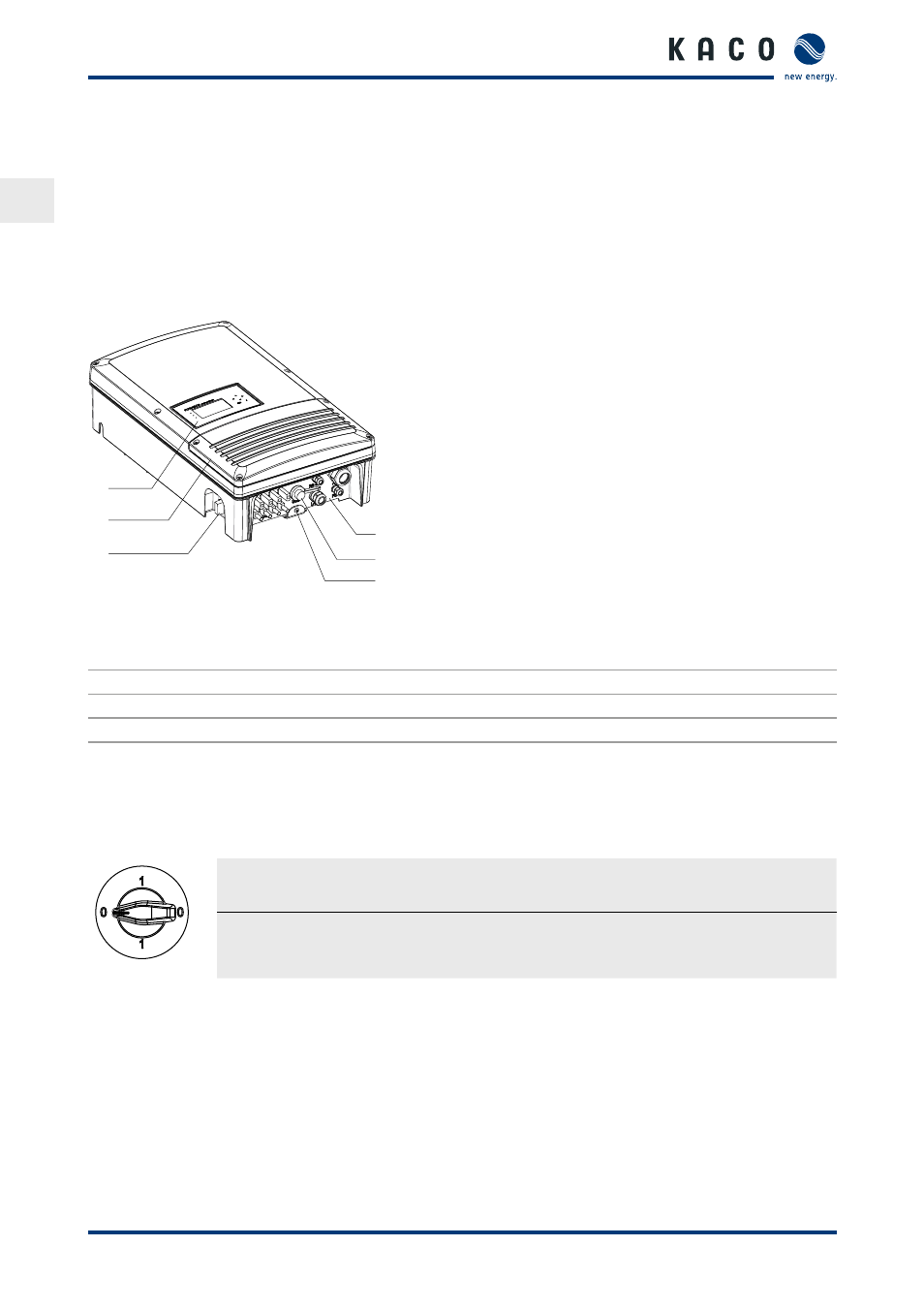
3.2.2 Inverter diagram
1
2
3
4
5
6
Figure 2: Inverter diagram
Key
1
Control panel
4
Connection board
2
Cover for the connection area
5
USB interface
3
DC isolator switch
6
Mounting plate
3.2.3 Mechanical components
DC isolator switch
The DC isolator switch is located on the bottom side of the inverter housing. The DC isolator switch is used to
disconnect the inverter from the PV generator in order to carry out service.
Disconnecting the inverter from the PV generator
"
Switch the DC isolator switches from 1 (ON) to 0 (OFF).
Connecting the inverter to the PV generator
"
Switch the DC isolator switches from 0 (OFF) to 1 (ON).
3.2.4 Interfaces
You configure the interfaces and the web server in the Settings menu.
The inverter has the following interfaces for communication and remote monitoring:
3.2.4.1 RS485 interface
Use this monitoring option if you cannot check the functioning of the system on-site on a regular basis, e.g. if
your place of residence is located a great distance from the system. To connect the RS485 interface, contact your
authorised electrician.
For monitoring your PV system using the RS485 interface, KACO new energy GmbH offers monitoring devices.