Installation, Unpacking, Panel mounting instructions – Precision Digital PD6000 User Manual
Page 15
Model PD6000 Analog Input Process Meter Instruction Manual
15
INSTALLATION
There is no need to remove the meter from its case to complete the in-
stallation, wiring, and setup of the meter for most applications.
Instructions are provided for setting up a 12/24 VDC powered meter to
operate from 12 VDC and for changing the transmitter power supply to
output 5 or 10 VDC instead of 24 VDC, see page 16.
Unpacking
Remove the meter from box. Inspect the packaging and contents for
damage. Report damages, if any, to the carrier.
If any part is missing or the meter malfunctions, please contact your
supplier or the factory for assistance.
Panel Mounting Instructions
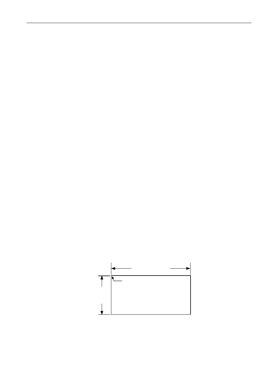
Prepare a standard 1/8 DIN panel cutout – 3.622" x 1.772" (92 mm x
45 mm). Refer to Figure 1 below, for more details.
Clearance: allow at least 6.0" (152 mm) behind the panel for wiring.
Panel thickness: 0.04" - 0.25" (1.0 mm - 6.4 mm).
Recommended minimum panel thickness to maintain Type 4X
rating: 0.06" (1.5 mm) steel panel, 0.16" (4.1 mm) plastic panel.
Remove the two mounting brackets provided with the meter (back-off the two
screws so that there is ¼" (6.4 mm) or less through the bracket. Slide the
bracket toward the front of the case and remove).
Insert meter into the panel cutout.
Install mounting brackets and tighten the screws against the panel. To
achieve a proper seal, tighten the mounting bracket screws evenly until me-
ter is snug to the panel along its short side. DO NOT OVER TIGHTEN, as
the rear of the panel may be damaged.
3.622" (92mm)
1.772"
(45mm)
Panel Cutout
to DIN 43700
Square Corners to 0.060"
(1.5mm) Max Radius
A
B
Tolerances:
A: +0.032 (+0.8mm)
-0.000 (-0.0mm)
B: +0.024 (+0.6mm)
-0.000 (-0.0mm)
Figure 1. 1/8 DIN Panel Cutout Dimensions
Refer to page
95 for mounting
dimensions