Connectors labeling, Power connections, Figure 7: power connections – Precision Digital PD6310 User Manual
Page 22: Ma out, Power, Signal, M-link, Relay4 relay3, Relay2 relay1
Model PD6210 & PD6310 Batch Controllers
Instruction Manual
22
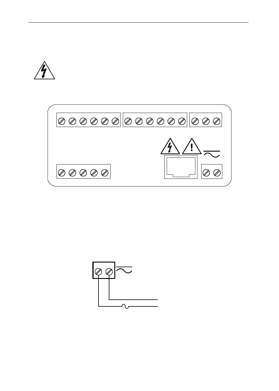
Connectors Labeling
The connectors’ label, affixed to the controller, shows the location of all
connectors available with requested configuration.
Warning!
Do not connect any equipment other than Precision
Digital’s expansion modules, cables, or controllers to
the RJ45 M-LINK connector. Otherwise damage will
occur to the equipment and the controller.
DW1815
R
I-
I+
MA OUT
1
3
2
POWER
+ -
SIGNAL
P-
COM
P+
V+
mA+
3
4
1
2
5
M-LINK
C
NO
NO
NC
NC
C
RELAY4
RELAY3
4
3
6
5
2
1
C
NO
NO
NC
NC
C
RELAY2
RELAY1
4
3
6
5
2
1
1 2 3 4 5 6 7 8
2
1
Figure 6: Connector Labeling for Fully Loaded PD6210
Power Connections
Power connections are made to a two-terminal connector labeled POWER
on Figure 6. The controller will operate regardless of DC polarity connec-
tion. The + and - symbols are only a suggested wiring convention.
AC or DC
POWER
Required External Fuse:
5 A max, 250 V Slow Blow
POWER
+ -
Figure 7: Power Connections