ProSoft Technology RLX-IFH24S-A User Manual
Page 77
RLX-IFHS ♦ RadioLinx Industrial Wireless
Guide to the RLX-IFHS User Manual
RadioLinx® Industrial Frequency Hopping Serial Radios
User Manual
ProSoft Technology, Inc.
Page 77 of 107
November 19, 2013
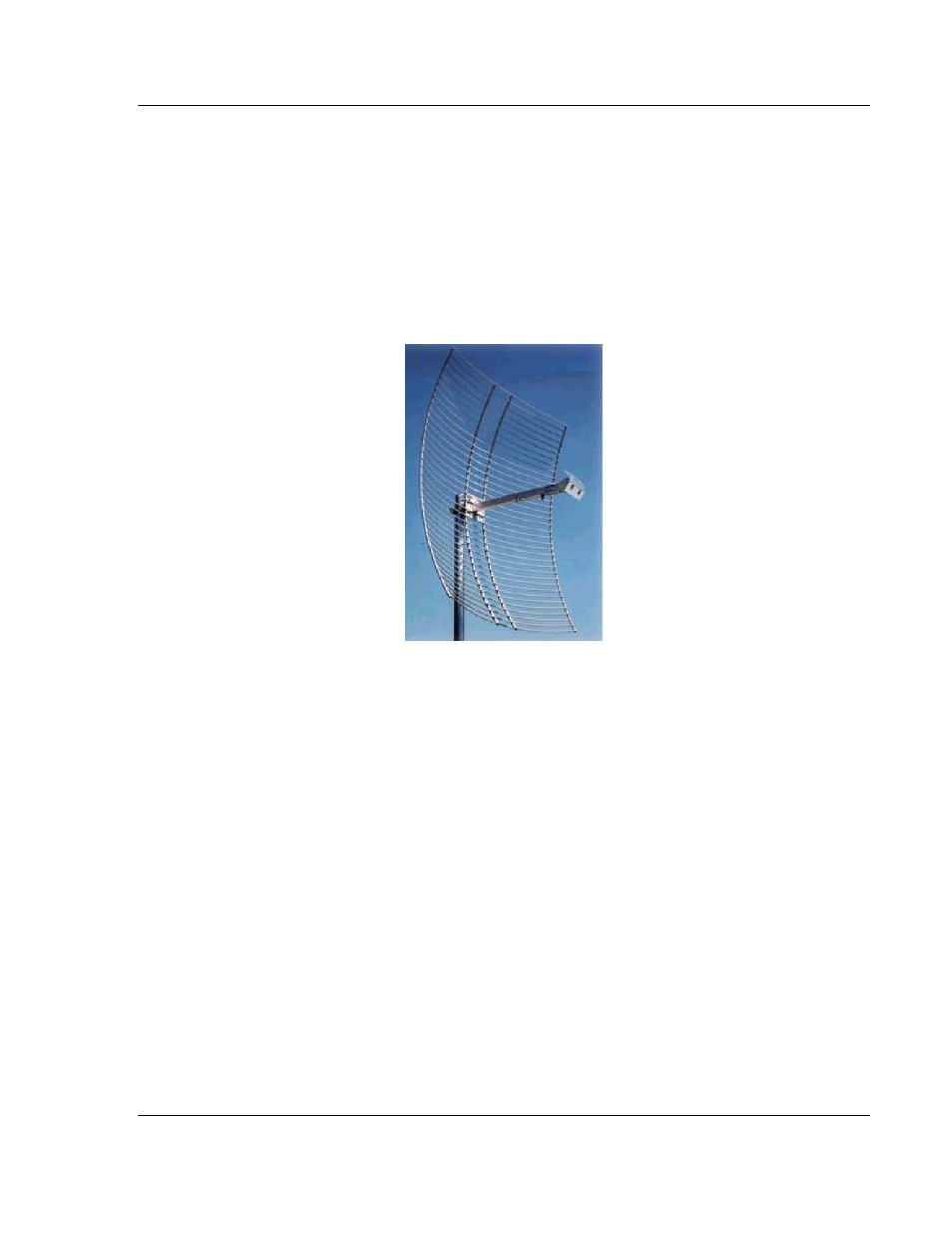
4.1.8 Parabolic reflector antennas
A parabolic reflector antenna consists of a parabolic shaped dish and a feed
antenna located in front of the dish. Power is radiated from the feed antenna
toward the reflector. Due to the parabolic shape, the reflector concentrates the
radiation into a narrow pattern, resulting in a high- gain beam.
The antenna pattern is a beam pointed away from the concave side of the dish.
Beamwidth and antenna gain vary with the size of the reflector and the antenna
construction. Typical gain values are 15 to 30 dBi.
The antenna polarity depends on the feed antenna polarization.
4.1.9 Adding bi-directional amplifiers
A bi-directional amplifier may be needed if an application requires long lengths of
coaxial cable to reach the antenna. The amplifier is designed to put maximum
transmit power right at the antenna and boost the received signal primarily to
overcome the cable loss. You can only use an amplifier from ProSoft Technology
that is specifically approved for use with the RLX-IFHS radio, and only in
countries where the amplifier option is approved.
The bi-directional amplifier is designed to operate with a coaxial cable loss
between the radio and amplifier of 6.5 dB to 20 dB. The output is always 1/2W,
regardless of the input level. With less than 6.5-dB loss, the amplifier maximum
input rating will be exceeded. With more than 20- dB cable loss, the amplifier will
not turn on.
Refer to Amplifier chart (page 77) to view the minimum and maximum lengths of
various cable types required when you use a bi-directional amp.
Refer to Amplifier Diagram (page 78) for an installation diagram of the amplifier
and its power supply.