ProSoft Technology RLX-IFH24S-A User Manual
Page 78
Guide to the RLX-IFHS User Manual
RLX-IFHS ♦ RadioLinx Industrial Wireless
User Manual
RadioLinx® Industrial Frequency Hopping Serial Radios
Page 78 of 107
ProSoft Technology, Inc.
November 19, 2013
Amplifier chart
The following chart lists the minimum and maximum lengths of various cable
types required when you use a bi-directional amplifier.
Cable Type
Cable loss/
100' (dB)
Minimum
length (feet)
Loss (dB)
Maximum
length (feet)
Loss (dB)
LMR195
18.2
36
6.5
109
20
LMR400
6.9
94
6.5
289
20
LMR600
4.4
148
6.5
454
20
LDF4-50A
3.9
167
6.5
512
20
LDF5-50A
2
325
6.5
1000
20
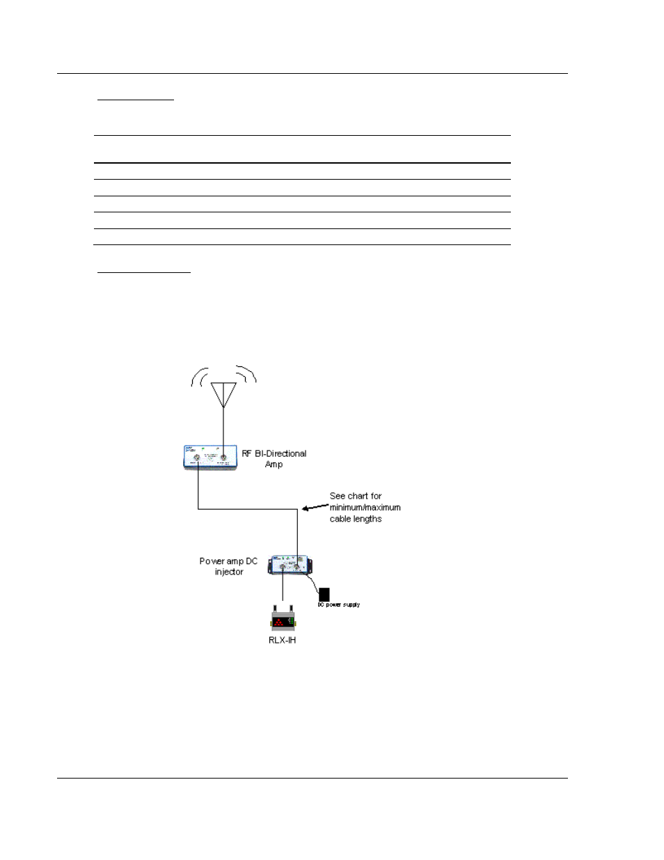
Amplifier diagram
The following illustration shows proper installation of the amplifier and its power
supply. The DC injector can be located by the radio, and the amplifier should be
at the antenna. The bi-directional amplifier is weather proof and can be mounted
outdoors. Refer to the bi-directional amplifier instructions for more information.
Refer to the amplifier chart (page 77) for minimum and maximum cable lengths.