Intek RheoVac CMS User Manual
Page 31
September 2013
27
© Intek, Inc. 2013
Revision D
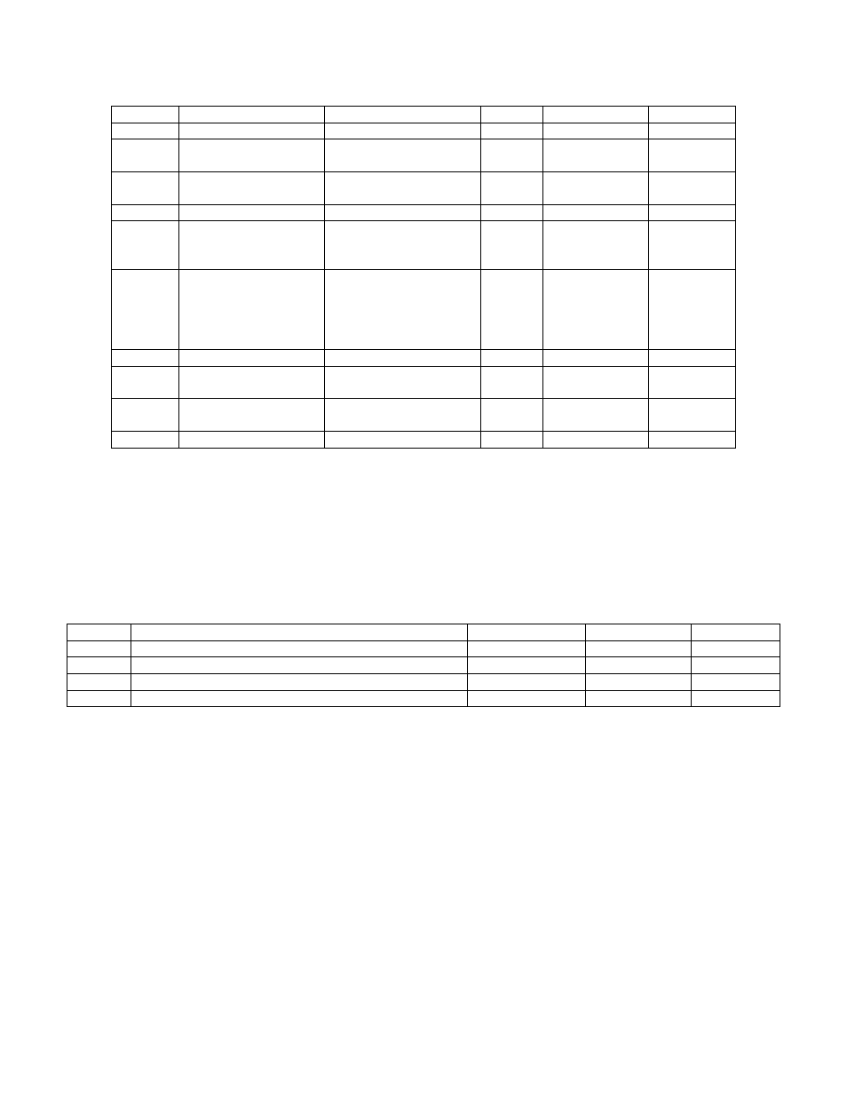
Table 8: Modbus server global settings
Address
Description
Allowed Values
Default
Format
Read Only?
0001
Restart Modbus Server
Write ‘1’ to restart
0
16-bit unsigned
No
0002
CMS Serial Port
Set to ‘0’ internally by
CMS System
0
16-bit unsigned
Yes
0003
Baud Rate
2400,4800,9600,14400,
19200 bps
9600
16-bit unsigned
No
0004
Data Bits
7 or 8
8
16-bit unsigned
No
0005
Stop Bits
0 = 1 stop bit
1 = 1.5 stop bits
2 – 2 stop bits
2
16-bit unsigned
No
0006
Parity
0 = No Parity
1 = Odd Parity
2 = Even Parity
3 = Mark Parity
4 = Space Parity
0
16-bit unsigned
No
0007
Modbus Address
1 – 255
1
16-bit unsigned
No
0008
Communication Mode
0 = RTU
1 = ASCII
0
16-bit unsigned
No
0009
Conversion Mode
0 = Multiplied Integer
1 = Single Float
1
16-bit unsigned
No
0010
Number of Probes
1 – 255
1
16-bit unsigned
Yes
4.2.2.2
Modbus data settings (Multiplied Integer Mode)
The values listed in Table 9 are examples of how the Modbus server stores “Multiplied Integer”.
“Multiplied Integer” mode can be enabled by writing a “0” to register 09. The address for the multiplier
is the holding register equivalent of the input register parameter it is multiplying. These register values
determine the power of 10 that is used to multiply each parameter (effectively shifting the decimal point)
before it is transmitted as a 16-bit unsigned integer.
Table 9: Modbus example data holding registers
Address
Description
Allowed Values
Default
Read Only?
8001
Multiplier power for TC1-1
0 – 3
16-bit unsigned
No
12005
Multiplier power for RheoVac MSP Actual Volume Flow
0 – 3
16-bit unsigned
No
12007
Multiplier power for RheoVac MSP Total Mass Flow
0 – 3
16-bit unsigned
No
12009
Multiplier power for RheoVac MSP Water Vapor Flow
0 – 3
16-bit unsigned
No
4.2.2.3
Modbus data registers (Multiplied Integer Mode)
When in Multiplied Integer Mode, the CMS data values are multiplied by a power of ten
specified in the registers listed in Table 9. The resulting values are then transmitted as 16-bit unsigned
integers. Each value therefore needs only 1 register (2 bytes) of allocated space. In this mode, the data
registers are allocated in pairs, with each data value followed by the multiplication power corresponding
to it. For example, assuming all multiplier registers are set to 3, the RheoVac MSP Pressure is
transmitted as follows:
RheoVac MSP Pressure (probe reading) = 1.257
Input Register 12011 (RheoVac MSP Pressure) = 1257
Holding Register 12011 (Multiplier Value) = 3
All other instruments can be calculated the same way substituting the correct address in place of
12011. The addresses for each instrument can be found in SECTION 8 - CUSTOM INFORMATION.