Connecting the motor, 16 bluac5 s/q hardware manual – Applied Motion BLuAC5-Q User Manual
Page 16
16
BLuAC5 S/Q Hardware manual
920-0049 Rev. C
12/8/2014
Connecting the Motor
WARNING: Never connect or disconnect the motor while the power is on.
Applied Motion Products motor:
To connect an Applied Motion servo motor to your BLU Servo, you’ll need a set of mating
cables called the BLUENC and the BLUMTR-FA.
You must use the “FA” (filtered) motor cable for proper operation of the drive. The
green wire of the cable must be connected to the chassis ground screw of the BLUAC5.
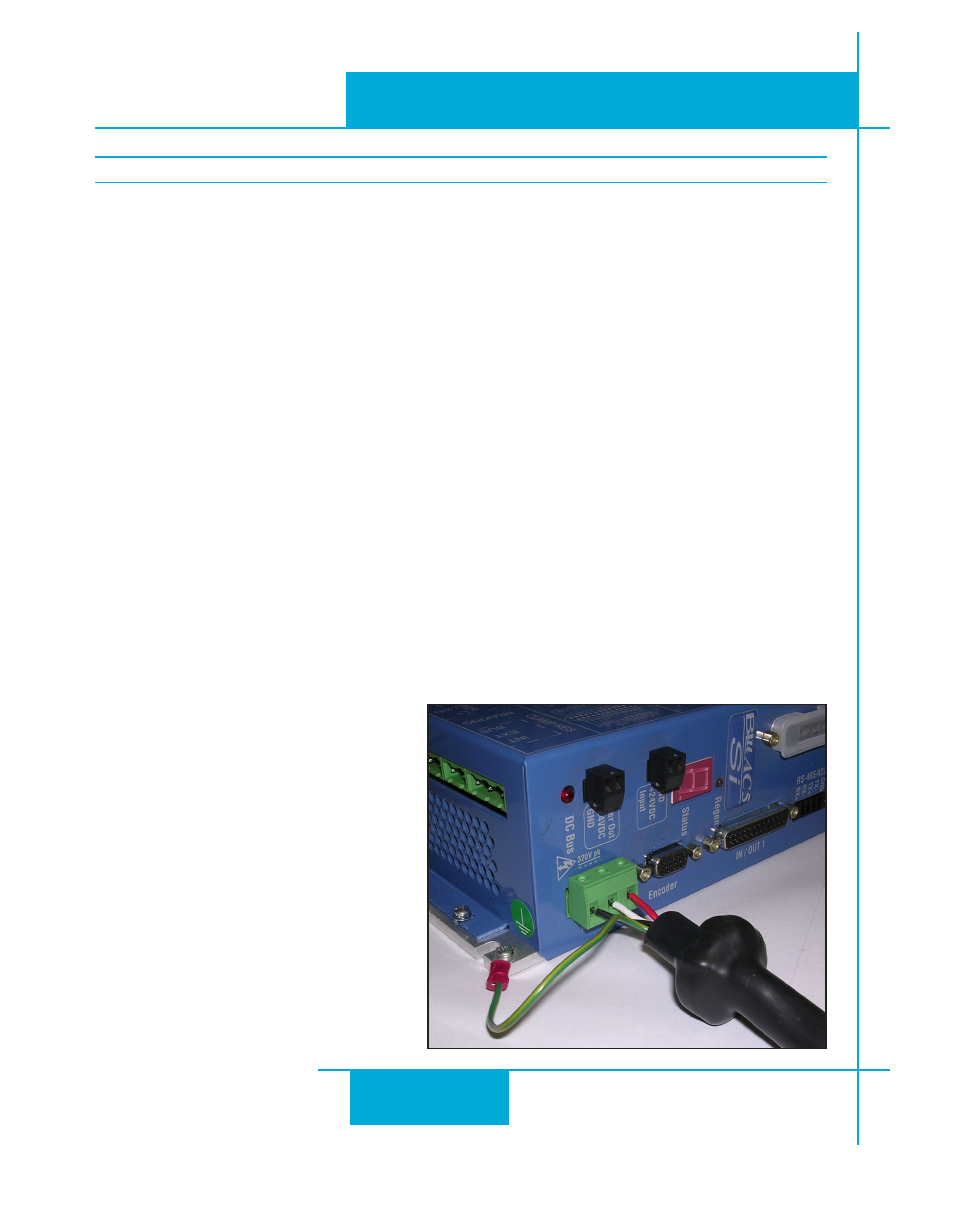
Connect the small motor connector to one end of the motor cable. The other end of the
BLUMTR-FA has lead wires that connect to the drive’s screw terminal connector as follows:
A = red wire
B = white wire
C = black wire
Connect the green wire and the bare “drain” wire to the chassis ground screw.
Connect the large motor connector to one end of the BLUENC cable. The other end of the
BLUENC plugs into the BLU servo.
For J-Series motors, use 3004-301-3M and 3004-307-3M cables (one of each).
Non-Applied Motion motor:
Connect the motor leads to the screw terminal connector as follows:
A = motor phase A, R or U
B = motor phase B, S or V
C = motor phase C, T or W
Connect the ground wire to the chassis
ground screw.
For proper drive operation, you must use
a well shielded, properly grounded cable.
Ferrite filtering is highly recommended
and is essential if your application is
intended to comply with EMC directives
such as the CE Mark. Please contact
Applied Motion Products for technical
advice before connecting a non-Applied
Motion motor.