In/out 1 connector, Summary of input signals, In/out 1 connector pin diagram – Applied Motion BLuAC5-Q User Manual
Page 20: 20 bluac5 s/q hardware manual
20
BLuAC5 S/Q Hardware manual
920-0049 Rev. C
12/8/2014
IN/OUT 1 Connector
The BLuAC5-S and BLuAC5-Q servo drives have seven digital inputs, one analog input and
three digital outputs located on the IN/OUT 1 connector. All inputs and outputs are program-
mable using the Quick Tuner software. They can also be configured “on the fly” using SCL or
Q commands.
Summary of Input Signals
X1/STEP & X2/DIR: digital 5V differential inputs for commanding position or encoder follow-
ing.
X3 - X7 are 12-24V single ended inputs:
X3/Servo Enable: Enables and disables the motor and servo system. Can be programmed
for active closed or active open. Note: When connected to Quick Tuner this input can be
overridden by the software.
X4/Alarm Reset: Close this signal momentarily to reset a drive fault (alarm).
X5: general purpose programmable input
X6/CCWLIM & X7/CWLIM: can be used to inhibit motion in a given direction, forcing the
motor and load to travel within mechanical limits.
Analog In: ±10V analog torque, velocity or position command signal. Can also be configured
for +10V, +5V or ±5V signals.
BLuAC5-SE and -QE drives provide an additional 8 digital inputs and one analog input on the
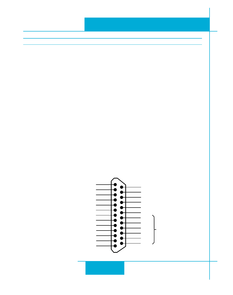
IN/OUT 1 Connector Pin Diagram
X COMMON
X7 / CW Limit
X3 / Servo Enable
X5
X4 / Alarm Reset
Analog IN-
Analog IN+
X2 / DIR /CCW Jog-
X2 / DIR /CCWJog+
X1 / STEP / CW Jog+
X1 / STEP / CW Jog-
GND
GND
A+
A-
B+
B-
Z+
Z-
+5V OUT
Y COMMON
Y3 / FAULT
Y2 / INPOSN
Y1 / BRAKE
18
17
16
15
14
13
12
11
10
9
8
7
6
5
4
2
3
1
19
20
21
22
23
24
25
Encoder
Outputs
X6 / CCW Limit