Connecting a single-ended encoder, Connecting single-ended hall sensors, 19 bluac5 s/q hardware manual – Applied Motion BLuAC5-Q User Manual
Page 19: Single ended encoder, Encoder connector, Single ended hall sensors
19
BLuAC5 S/Q Hardware manual
920-0049 Rev. C
12/8/2014
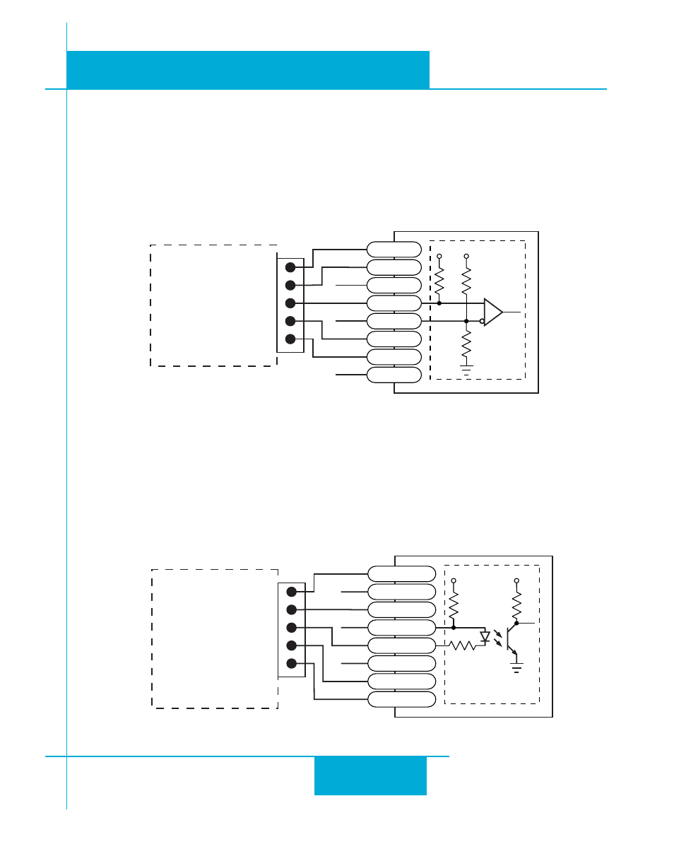
Connecting Single-Ended Hall Sensors
Single-ended Hall sensors may be connected to the servo drive as shown below. The out-
put of the Hall sensors must be able to “sink” 10ma of current in order to properly drive the
hall sensor inputs. Typically “Open Collector outputs are best suited to driving the hall sensor
inputs.
Connecting a Single-Ended Encoder
Single-ended encoders may be connected to the servo drive as shown below. It some cases
this may cause loss of encoder data. Typically single ended encoders source impedance is
high and cannot drive a terminated transmission line. Because of this single-ended signals
may be more susceptible to “Ground” and induced noise.
NOTE: Not recommend in “High Noise” environ-
Single Ended Encoder
encoder A (3)
GND (1)
+5VDC (4)
encoder B (5)
index (2)
Encoder Connector
(8) GND
(5) Z+
(3) B+
(1) A+
(7) +5V
(4) B-
(6) Z-
(2) A-
NC
NC
NC
3.3k
Vcc
330
Vcc
220
Typical Input
Circuit
NOTE: Not recommend in “High Noise” environments
Single Ended Hall Sensors
V or B
U or A
GND
W or C
Encoder Connector
(7) +5V
NC
NC
NC
220
Vcc
220
Typical
Input
Circuit
+5V
(8) GND
Open Collector
Outputs
Vcc
(10) Hall 1-
(9) Hall 1+
(13) Hall 3+
(14) Hall 3-
(12) Hall 2-
(11) Hall 2+